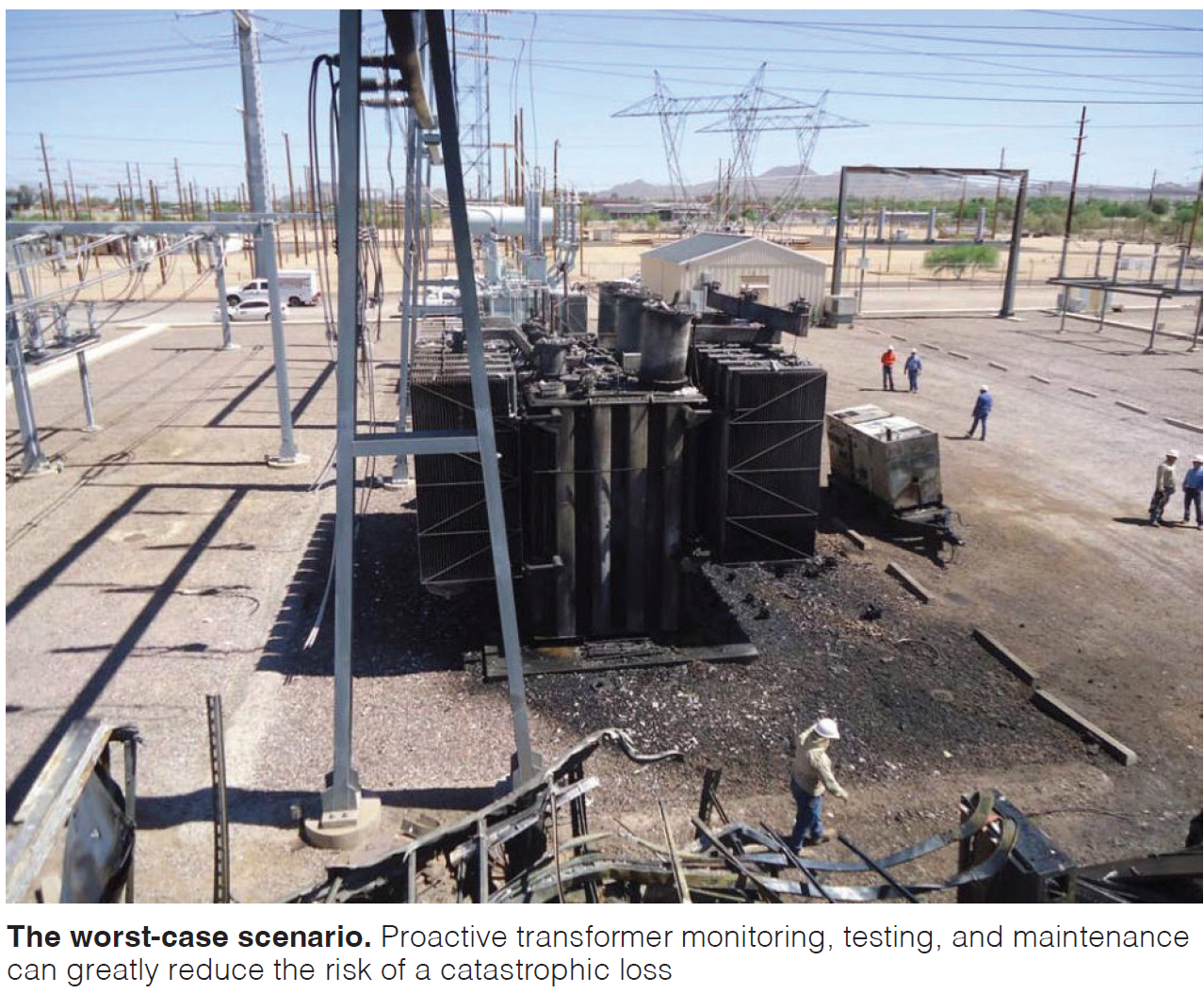
Tip: Implement a structured visual inspection program for switchyard high-voltage equipment between scheduled maintenance intervals, supported by periodic thermal and acoustic diagnostics, to catch early indicators before they become forced outages.
Bryan Miller of RATTLIR LLC recently called CCJ editorial offices to flag something he keeps seeing at gas turbine sites: a significant gap between what standard compliance programs cover and what is actually happening to high-voltage equipment in plant switchyards.
PRC-005-based maintenance programs are solid. They confirm that protection schemes will operate correctly during a fault. Relay tests, battery inspections, CT and PT validations, and trip circuit checks all serve essential functions. Miller is not disputing that. His concern is narrower: these programs were not designed to track how equipment is aging or how mechanical stresses are developing in the months between test cycles.
The switchyard is full of mechanical interfaces. Bolted connections loosen under thermal cycling. Disconnect blades lose contact pressure. Grounding components corrode. Surge arresters absorb moisture. These are slow-moving degradations, not sudden failures, and they often escape detection until something trips or fails outright.
Miller developed a high-voltage visual inspection checklist specifically for switchyard equipment at gas turbine sites. He also assembled a failure modes reference table that describes what these failures look like in the field and, critically, why they are often missed. CCJ reviewed both documents along with Miller’s white paper on switchyard visibility and predictive maintenance. The picture that emerges is consistent: early indicators are there. Plants are not always seeing them.
What the failures look like
Miller’s failure modes table documents seven categories of high-voltage assets and the early symptoms each typically produces before a fault occurs. Several entries share a common trait: the equipment looks fine during normal operation and inspection, but heating, degradation, or both develop under load or over time.
- Conductors and terminations show increased resistance from strand fatigue, oxidation, or poor compression. Early symptom is uneven or localized heating under load, sometimes presenting as phase imbalance. The failure is easy to miss because the hardware appears visually intact. Heating may not be present during no-load conditions.
- Disconnect blades and jaw contacts lose contact pressure or suffer surface degradation. The early symptom is phase-specific heating at the blade-to-jaw interface. Again, the equipment operates normally in most respects. The heating signature only becomes apparent during load transfer or sustained operation at elevated output.
- Bushings, both transformer and breaker types, degrade from internal cracking, moisture ingress, or surface contamination. Early symptoms include subtle partial discharge, localized heating, or tracking visible under wet conditions. Because the damage is internal, the exterior often appears normal. Escalation can be rapid once underway.
- Surge arresters develop moisture ingress or seal degradation. Early symptom is localized heating or external cracking. Miller notes that arresters often look intact after moisture ingress begins. Failure may not occur until a surge event triggers the compromised unit.
- Grounding and bonding components corrode or develop high-resistance connections. The early symptom is no visible symptom at all. These components are considered non-energized and often fall outside routine inspection scope. A failed ground does not announce itself until a fault event.
- Structural components, including masts, air terminals, and supports, corrode or loosen gradually. Early indicators are minor. Damage may be internal or weather-dependent, and deterioration progresses slowly without producing obvious operational signals.
Miller’s inspection checklist covers all of these asset categories. The checklist is organized in the sequence an inspector would encounter equipment walking through a switchyard: GSU, auxiliary and station service transformers, surge arresters, braided connections, CTs, electrical disconnects, circuit breakers, conductor and buswork, VT/PT, insulators, and station structures. Each section includes specific prompts.
For disconnect blades: look for signs of arcing, audible noise, ozone odor, or corona activity. Check whether blades are fully seated and aligned evenly across all phases.
For transformers: record winding and oil temperatures against historical maximums, check bushing oil levels, look for tracking or contamination on bushings, inspect desiccant breathers.
For conductors: look for broken strands, excessive sag, and abnormal movement or contact with nearby structures.
For insulators: check for cracks, chips, contamination buildup, and proper corona ring alignment. For station structures: verify lightning rods and ground wires are intact, look for animal nests or vegetation that could affect clearances.
The goal of this checklist is not to replace established maintenance procedures. It is to help operators and maintenance personnel recognize early indicators of abnormal equipment conditions between scheduled maintenance intervals, when compliance-based programs are not looking.
Thermal and acoustic imaging add coverage
Visual inspection alone has structural limits. Much of the critical switchyard hardware sits elevated. Ground-level observation can confirm gross condition, but it cannot clearly evaluate connection surfaces, contact integrity, or subtle changes at height. This is where periodic diagnostic assessments provide complementary value.
Thermal imaging is most effective as a comparative tool. NETA and NFPA standards reinforce this by focusing on temperature differentials, delta T, between similar components under similar loading conditions. A 10-degree differential between phases on the same bus structure warrants investigation. A 15-degree differential may warrant corrective action. Absolute temperature is less useful; delta T under controlled load conditions is the diagnostic signal. In the field, thermal imaging can reveal high-resistance connections from looseness or corrosion, load imbalance across phases, degraded contact surfaces in disconnects, deteriorating compression terminations, and localized heating at developing failure points.
Ground-based thermal inspections provide a useful baseline. Aerial thermography, typically performed using drones, improves the evaluation of elevated components by reducing the influence of ground-level background temperatures and allowing closer approach to specific connections and hardware interfaces. This is not a replacement for ground-based inspection. It is a complementary tool that increases confidence in the assessment of hardware that cannot be clearly seen from below.
Acoustic imaging addresses a different failure mode: electrical discharge that does not present as heat. Corona, surface tracking, and partial discharge can occur on energized equipment without obvious visual or thermal indicators. These conditions are influenced by contamination, moisture, insulation condition, and environmental exposure. They develop at connections, insulators, and terminations throughout the switchyard. Acoustic imaging detects the high-frequency sound signatures associated with electrical discharge, allowing inspectors to locate and assess areas of electrical stress directly.
Miller’s white paper makes a practical observation about the cumulative value of these approaches. When diagnostic information is available ahead of a planned outage, maintenance scope can be better defined, materials more accurately planned, and resources more effectively allocated. Unexpected findings during the outage are reduced. In some cases, identifying a degrading component early allows it to be addressed before it fails and forces the outage itself. Preventing a forced outage avoids the operational disruption, safety risk, and cost associated with reactive work.
Applying this at your facility
Miller’s checklist and the supporting failure modes table are tools designed for use during routine walkdowns. The checklist is straightforward to integrate into existing operator and maintenance routines. It does not require special access, additional clearance, or outages to execute. It requires someone walking the switchyard with a checklist, adequate light, and enough familiarity with the equipment to recognize when something looks different than it did last time.
The thermal and acoustic diagnostic layers are periodic assessments rather than continuous monitoring. Miller recommends incorporating these into the maintenance plan on a schedule aligned with unit cycling patterns and historical failure experience. Aerial thermography, where permitted by site safety and regulatory requirements, is particularly useful for pre-outage inspections where it can influence scope decisions before maintenance teams are on site.
The inspection hierarchy Miller proposes is: structured visual walkdowns as the consistent baseline, thermal imaging to identify thermal anomalies and phase imbalance under load, and acoustic imaging to detect electrical discharge activity that thermal methods do not capture. Together, these approaches cover more failure modes than any single method alone.
Risks and caveats
No inspection program eliminates failure risk. These approaches improve the probability of detecting early indicators before they become forced outages, but several conditions reduce their effectiveness.
Thermal imaging requires adequate load on the equipment being inspected. Inspections performed on lightly loaded or offline equipment will not reveal the heating signatures that indicate developing resistance or imbalance. Consistent loading conditions across inspection intervals are necessary to make meaningful comparisons over time.
Acoustic imaging is sensitive to ambient noise and wind. Results are most reliable during low-wind conditions and may require repeat assessment if initial findings are ambiguous.
Visual inspection quality depends heavily on the inspector’s familiarity with the equipment. An inspector who does not know what normal looks like is less likely to recognize early indicators of change. Cross-training operators and technicians on what to look for improves consistency.
Grounding system degradation, which Miller identifies as one of the most frequently missed failure categories, produces no pre-fault symptoms that visual, thermal, or acoustic inspection can detect. Periodic ground resistance testing addresses this gap but falls outside the routine walkdown scope.
Corona ring orientation and electric-field grading hardware are not visually obvious failure modes. Damage develops gradually and may not affect equipment appearance. Acoustic imaging provides the best coverage for these conditions.
Animal intrusion and vegetation growth can produce rapid deterioration in clearances, but the triggering event may not occur during a scheduled inspection window. Regular inspection intervals, rather than infrequent or event-driven walkdowns, provide better coverage for these dynamic conditions.
Bottom line. The gap Miller identified is not a compliance gap. PRC-005-based programs confirm fault response correctly. The gap is a condition-monitoring gap: slow-developing mechanical degradation in the switchyard is not always visible to the programs designed to confirm protective function. Structured visual inspections, periodic thermal imaging, and acoustic diagnostics together provide broader coverage. They shift the inspection focus from obvious failures to early indicators of change, which is where planned outages beat forced outages every time. CCJ