


Not meeting expectations? Fix or replace. Don’t accept subpar performance
There are several reasons your inlet cooling system may not be meeting expectations. Among them:
- Poor O&M practices.
- Installed equipment not utility-grade.
- Old age: System antiquated or obsolete.
- Inappropriate technology for plant’s ambient conditions and/or for meeting the terms of the current power-supply contract.
A proper inspection, as described in the first section of this report, provides information vital to deciding whether it is in your company’s best interest to overhaul the existing inlet cooling system or to replace it – in kind, or with another technology.
If you’re involved in this process, it might be worthwhile to review the basics of the alternative inlet cooling technologies and to learn more about the latest offerings from the leading suppliers. A good place to begin is by reading the thumbnails below of the cooling methods used most frequently on the front end of gas turbines dedicated to power production. More detail is available on the website of the Turbine Inlet Cooling Assn (TICA) at www.turbineinletcooling.org (sidebar).
Evap coolers are specified most often. They cool via evaporation of water from the wetted media into the GT inlet air. Humidification is accomplished as water flows over the wetted media and air passes through it. The water may require treatment, depending on the GT manufacturer’s specifications. A honeycomb-type medium is most common.
Wetted media can cool the inlet air to within 85% to 95% of the difference between the ambient dry-bulb and wet-bulb temperatures. It is one of the least-cost cooling options, despite its high water consumption. Primary disadvantage is that the extent of cooling is limited by the wet-bulb temperature and is, therefore, weather- and climate-dependent. Wetted media is most efficient in hot, dry climates and less effective when ambient humidity is high.
Fogging is the second most popular evaporative technology. It saturates the GT inlet air by spraying very fine droplets of water into the air stream. Droplet size depends on the desired evaporation time and ambient conditions. Fogging typically requires demineralized water.
Fogging systems can cool the inlet air to within 95% to 98% of the difference between ambient dry-bulb and wet-bulb temperatures, so it’s slightly more effective than the wetted media. The capital cost is comparable to that for the wetted media and the technology has similar limitations and disadvantages.
Over spraying, also known as wet compression, adds more “fog” to the inlet air than can be evaporated under ambient conditions. The air stream carries the excess fog into the compressor section of the GT where it evaporates, cooling the compressed air further and creating extra mass for boosting the GT output beyond that possible with the other two evaporative technologies discussed above.
Chillers can cool the inlet air to much lower temperatures than those possible with evaporative cooling and can maintain any desired inlet air temperature down to 42F, independent of ambient wet-bulb temperature. It works this way: Inlet air flows across cooling coils within which either chilled water or refrigerant is circulated. Mechanical chillers powered by electric motors or steam turbines generally are preferred over absorption systems for powerplant service.
Cold water can be supplied directly from a chiller or from a thermal energy storage (TES) tank containing ice or only chilled water. TES typically is specified when cooling is required for a limited number of on-peak hours, because it reduces the chiller plant’s installed capacity requirements and overall capital cost. Also, TES allows the plant to export maximum power on peak because it is charged at night using off-peak electricity.
The primary disadvantages of mechanical refrigeration compared to evaporative cooling technologies: Higher capital cost, larger footprint, and higher parasitic power load. The impact of its power requirement may increase overall plant heat rate if TES is not used.
It’s not just about technology. The editors caught up with John Kraft, president, Caldwell Energy Co, Louisville, at a recent meeting of the Combustion Turbine Operations Task Force (CTOTF) and asked him to put on his TICA vice chairman’s hat to discuss the challenges GT owner/operators face with respect to inlet-cooling decisions. By way of background, Caldwell is well known in the industry for its fogging systems.
Inlet cooling 101: TICA offers a refresher
Today’s competitive generation business presents many challenges to owner/operators of GT-based powerplants. One is maximizing output and revenue, especially during the warm months when power prices typically are highest. Perhaps the most efficient way of boosting output is by cooling combustion air before it enters the compressor, says Dharam (Don) Punwani, president of Avalon Consulting Inc, Naperville, Ill, and executive director of the Turbine Inlet Cooling Association (TICA).
Recall that the power output of a GT is directly proportional to, and limited by, the mass of a volumetric flow rate of air. But while the volumetric capacity is fixed, the mass flow rate of air delivered to the compressor decreases as ambient temperature rises above the rated-capacity design point (so-called ISO conditions, 59F and sea level).
The actual impact of ambient air temperature on output depends on GT type, age, condition, etc. Information available at www.turbineinletcooling.org, the association’s website, notes that aeroderivative engines are more sensitive to ambient temperature than frame machines.
“Turbine inlet cooling: An energy solution that’s better for the environment, ratepayers, and plant owners,” a white paper containing many charts and tables useful for go/no-go decision-making, notes that an increase in ambient from 59F to 90F can reduce the rated output of an aero with a 30:1 compression ratio by as much as 13%. By contrast, for an older frame with a 10:1 compression ratio the power loss would be 6%.
It is possible to increase the power output of a GT above its rated capacity by cooling inlet air below 59F. For the aero, delivering 50F air to the compressor would deliver 102.5% of rated output; for the frame, slightly less. But keep in mind that the generator also must be capable of operating above its rated output.
TICA’s mission is to promote the development and exchange of knowledge related to GT inlet cooling, which in the group’s words “provides a cost-effective, energy-efficient, and environmentally beneficial means to enhance power generation capacity and performance.” A particularly valuable contribution of the website is its bibliography of publications on turbine inlet cooling dating back two decades. You can get there by clicking “Library & Links” on the horizontal toolbar at the top of the page.
Many companies offering products and services for inlet cooling are members of the association and they can be accessed via the website. You’ll probably recognize the names of several companies and people in lineup of officers and board members below:
- President: Trevor Richter, VP, Stellar Energy Systems.
- Vice President: Annette Dwyer, regional sales manager, Munters Corp.
- Secretary: Russ Thompson, director of industrial business, Turbine Air Systems.
- Treasurer: Pat Graef, engineering and development manager, Munters Corp.
- Chairman, Board of Directors: Kurt Leibendorfer, senior VP, Stellar Energy Systems.
- Vice Chairman: John Kraft, president, Caldwell Energy Co.
- Companies not listed above and represented on the board: The Cool Solutions Company, Chicago Bridge & Iron Co, Natgun Corp, Baltimore Aircoil Co, Pasteris Energy Inc, Danfoss-Nessie High Pressure Water Systems, and Johnson Controls Inc.
Kraft summed it up this way: Many considerations impact decisions on turbine inlet cooling; technology is only one of them. First concern of the owner: Does it make economic sense to increase plant output? If not, put away your paper and pencils.
If you pass the owner’s “dollars and sense” test, carefully read the plant’s operating permit. Anything in it that would militate against the project envisioned?
Next, what will the regulatory authorities think about your plan to boost output? If you will burn more fuel, the project probably will not be viewed favorably. Permitting could be very difficult, possibly a deal killer. In Kraft’s words, permitting is a negative driver for TIC improvements.
Water use may be an issue in some areas, particularly if a chiller package with wet cooling is specified. Air-cooled condensers might not work financially.
If you’re still in the game at this point, call on the turbine OEM to be sure the proposed inlet-cooling system is suitable for your unit without operating restrictions. Wet compression is one alternative that could require careful analysis by the manufacturer’s engineers.
There are many “ifs” in the foregoing because that’s the reality of trying to improve a permitted plant. Where the economics are compelling for a given project, you generally can overcome regulatory concerns with hard work and an accommodating design. The Palomar case history in the chiller section near the end of this report is a case in point.
Good idea, but not at this time. The first thing Kraft said regarding the viability of capacity improvements offered by inlet cooling was “It depends on how you get paid.” The editors learned this first hand when they met with the engineering manager for a 2 × 1 F-class combined cycle equipped with evap coolers. Two plants nearby – one about 25 miles away, the other about 50 – are equipped with chillers. One of the two converted from an evap cooler because of the value proposition.
The manager had a conversion plan ready for his plant and was just waiting for the opportunity to implement it. In this case, the owner assigned a low value for new capacity given other generating resources in the area and its contract with the ISO. The conversion project is viewed positively by management, but not justifiable at this time. Swapping out the evap coolers for chillers here would be the capacity equivalent of adding an LM6000. You could think of the chillers as a virtual peaker.
But the motivation for doing the project could change. For example, should quick-response capacity be required to back up renewables, grid reliability rather than economics would be the reason to move forward. Delays in licensing new generating facilities to replace the existing plants being forced into retirement for environmental reasons might be another reason to implement the chiller solution.
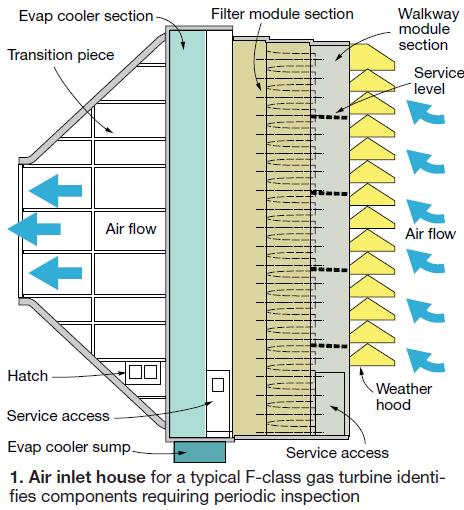
Evap coolers
Virtually all evaporative coolers for GT inlet service are of the recirculating type and located downstream of the filtration system. The required water inventory is maintained in a sump at the bottom of the air inlet house (refer back to Fig 1). Water is pumped from the sump to a distribution header at the top of the cooler and it falls by gravity down through the media and back to the sump.
Air flows approximately perpendicular to the falling water and its sensible heat is transferred to the water, becoming latent heat as water evaporates. Resulting water vapor mixes with the air stream, carrying the latent heat along with it.
The dry-bulb temperature of the air is reduced because it gives up sensible heat. Wet-bulb temperature is not affected by the absorption of latent heat because water vapor enters the air at the wet-bulb temperature.
System chemistry is maintained in much the same way as it is for a wet cooling tower. Water specifications provided by the evap cooler supplier, plant chemist, and/or an outside consultant have, at a minimum, limits on turbidity, pH, hardness as calcium carbonate, and the concentration of sodium plus potassium. Makeup water is added to replace evaporation and blowdown losses.
Makeup water specifications are important as well. It is important not to use straight demineralized water in evap coolers as you would in a fogging system. Such aggressive water softens the media and may damage the evap cooler framework, depending on the material used. Some plants use city water where available and of suitable quality, others might mix demineralized water with that from another source. Consult the media supplier to be sure you’re going down the right path.
Spend quality time evaluating media alternatives both for new and existing systems; product offerings are always changing, usually for the better. Regarding the evap cooler now serving at your plant, recall that suppliers recommend changing media after three to five years of service to maintain top performance.
Several types of media for GT service are offered by Munters Corp, Ft Myers, Fla, considered by most users as the industry leader (www.munters.us).
The company promotes a special product for gas turbine applications, citing high efficiency, low pressure drop, low drift, and other attributes. It reportedly can be used in applications with average face velocities of up to 750 ft/min.
Finally, don’t forget the drift eliminator. While water carryover from a properly designed, installed, operated, and maintained evap cooler should be negligible, critical parameters change over time and a drift eliminator immediately downstream of the media is necessary to protect the health of both the air inlet system and the compressor.
Fogging out, evap cooler in
Savvy powerplant managers generally know what works best for improving performance, safety, etc. But it often takes a long time to get management buy-in for ideas requiring significant expenditures. To be fair, executives must be careful how they spend the owners’ money; good idea or not, return-on-investment criteria are unforgiving.
A case in point is a 7FA-powered 2 × 1 combined cycle located in the Mid-Atlantic region that began commercial operation in 2003 with the OEM’s fogging system installed in each of the coated carbon-steel air inlet houses. The operations team leader for this facility told the editors the fogger was ineffective.
Thinking on the deck plates was that the relatively large droplets created by the nozzles were not evaporating as designers intended and the power boost with the fogger in service was marginal at best. So the system was not used. An editorial pause here: The names of the owner, plant, and operations team leader are not presented because there was insufficient time for corporate review.
Four years after COD, the business case for replacing the fogging system with an evap cooler was accepted. On the ideal day – 85F and 45% relative humidity – the plant would produce an additional 15 MW; the improvement on any given day typically would be between 5 and 10 MW. Conservative calculations put the payback at around three years with the plant in cycling service. It is now running more hours, which translates to a faster return on the investment.
The project was bid competitively and Munters was selected. Contract labor installed the evap cooler in three months; however, the plant was shut down for only half that time. The 45-day outage had been planned for total plant overhaul. Work involved extending the air inlet house and ductwork modifications.
The plant owner was proactive at the design stage. Its highly experienced central engineering team reviewed evap-cooler best practices company-wide to assure the system installed would meet expectations. Maintainability was a key goal. Adequate space and platforms were built into the air inlet house to facilitate inspection, media replacement, and maintenance.
Plus, the fluid-handling skid was placed at ground level for easy access to system pumps, water sampling points, instrumentation, etc. Stainless steel was specified for all piping and pump impellers for long life. A new makeup system was installed for city water to replace the demin-water system required by the foggers. Tap-water quality is good at this location and can be used for evap-cooler service without pretreatment.
The first-year inspection and system flush were completed only a couple of weeks before the editors called the plant. No deficiencies were noted. A Munters representative was on hand for the inspection and compared the baseline water analysis with that done a year later. No significant change. The operations team leader praised the supplier’s effort on the project and continuing customer service.
Replace old-style evap cooler, air inlet system
When Greenwood Energy Center (GEC) was built in the mid 1970s, long-distance road running was just coming into its own and there were more than just a few people participating in their basketball sneakers (Nike was incorporated in 1972). Today, you’d probably be hard pressed to find anyone in canvas tops running a marathon. The reason is obvious: High-tech shoes are critical for success.
The same is true in the generation business, which seems to grow more competitive by the day. Unless your facility has a great grandfathered grid deal, you’re just not going to dispatch ahead of GTs with modern “front ends” capable of wringing the last few Btus out of their fuel.
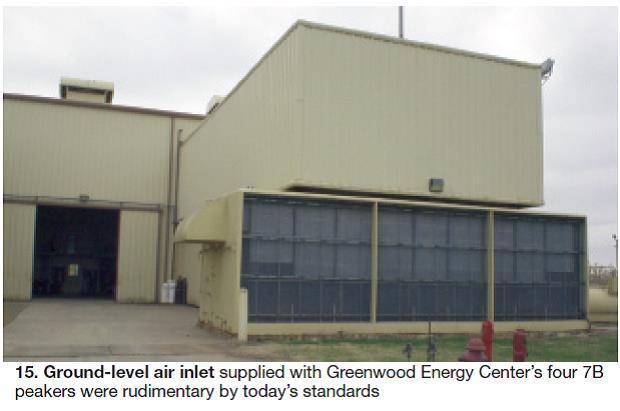
The first of GEC’s four simple-cycle, distillate-fired GE 7Bs began commercial operation in 1974, equipped with a rudimentary (by today’s standards) ground-level evap cooler familiar to many readers (Fig 15). In 1996, the units were converted to dual-fuel.
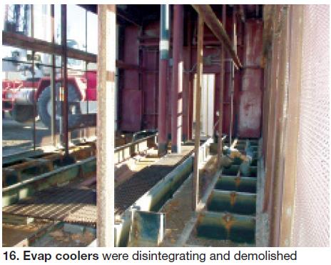
Problems attributed to age and continued use of old technology included the following:Corrosion of the internal perforated galvanized-steel wrappers for the air inlet houses was virtually impossible to arrest and metal flakes and chunks were being ingested by the compressor. Maintenance procedure was to scrape off loose metal during the annual spring outage, sweep it up, and run another year. Tom Miller, who manages the Combustion Turbine Dept for Missouri-based owner Kansas City Power & Light Co (KCPL), said Greenwood personnel were filling a 55-gal drum with debris annually (sidebar).
- Reduced peak output.
- Reduced efficiency.
- Compressor FOD (foreign object damage), requiring replacement of R1 blades.
- Snow blinding of barrier air filters during blizzards.
Bill Grace and his colleagues at Tulsa-based Braden Manufacturing LLC got their first glimpse at GEC’s air inlet challenges in 2005. He recalled that the owner, Aquila at the time, was leaning towards taking the inlet air house’s internal surfaces down to bare metal and coating with epoxy – a fast and inexpensive way to keep foreign material out of the compressor.
Greenwood Energy Center backgrounder
Kansas City Power & Light Co (KCPL), well known to long-time industry professionals, was reorganized under Great Plains Energy Inc in 2001, according to Ellen Flynn Giles, editor of the “UDI Directory of Electric Power Producers and Distributors,” published annually by Platts, a division of the McGraw-Hill Companies Inc.
Holding company Great Plains acquired Aquila Inc’s Missouri generating plants in July 2008 and combined KCPL’s Missouri assets and Aquila’s under KCP&L Greater Missouri Operations d/b/a KCP&L. Aquila had previously operated under the name UtiliCorp United Inc. Tom Miller, a member of the 7EA Users Group steering committee, manages KCPL’s Combustion Turbine Dept. He is responsible for a dozen 7Bs, 11 7EAs, three W501D5As, two FT4s, and one Frame 5 located in Kansas, Missouri, and Mississippi.
Miller’s affiliation with Aquila began in the mid 2000s when he was construction manager for the South Harper Power Plant, a peaking facility in Peculiar, Mo, which began commercial operation in 2005. He was appointed head of Aquila’s gas turbine assets in 2006 and transitioned to KCPL along with the assets he managed.
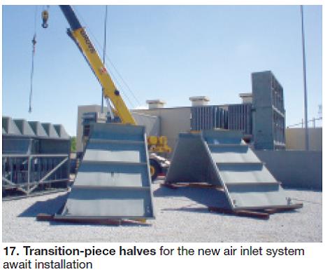
But a thorough engineering assessment revealed that the evap cooler and the inlet house had, practically speaking, reached end-of-life. The project then evolved from a repair job to a new intake system. Braden proposed replacing the ground level air inlet with an elevated system having Type 304 stainless steel internals. The company also suggested switching from barrier filters to a pulse-type filter house – this to prevent a unit trip on high delta p during a blizzard.
Braden was awarded a turnkey contract to install new filter houses on the four Greenwood engines – one at a time. The upgrades were completed between 2006 and 2008 (Fig 17).
The proverbial “fly in the ointment” for this project: There was no compressed air available for pulsing the filters. Aquila didn’t want the cost of a compressed air system added to the budget so engineers came up with the idea of tapping into the combustion wrapper. Certainly a viable idea, but that air was at about 750F and far too hot for cleaning filters.
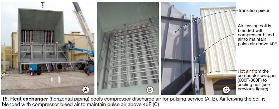
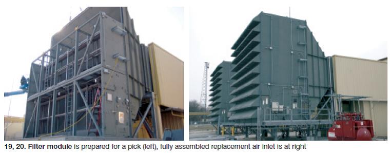 Miller said payback on the retrofit was faster than expected because the turbines produced an additional 3 to 4 MW each with the new evap cooler; the units get capacity payments (Figs 19, 20). Taking air from the combustor case for pulse cleaning has virtually no economic impact. The ability to run through the horizontal snowstorms that often occur in this part of the country is very important.The solution: A heat exchanger, installed in the filter house, to cool pulse air to 95F (Fig 18a and 18b). That worked fine until winter, when the plant experienced freeze-up of the pulse-air system. The fix was to blend some compressor bleed air with the air leaving the heat-transfer coil to maintain the temperature of pulse air above 40F (Fig 18c).
The editors spoke to Miller via a hands-free phone while he drove to one of the company’s plants in Mississippi, so the conversation went beyond retrofit of the air inlets. He said another major retrofit project for Greenwood was replacement of the OEM control system on each engine with Ovation®.
The controls solution from Pittsburgh-based Emerson Process Management, Power & Water Solutions was selected because the company had Ovation in its coal-fired plants and wanted to standardize on the platform to reduce costs. With Ovation the GTs are capable of running reliably on either gas or oil, or a mixture, and swapping fuels “on the fly.”
Installation of demisters for the lube-oil system, plus upgrades to the generator-excitation, relay-protection, lube-oil-cooling, and fire-suppression systems also have been completed in the last few years.
The company’s investments in its generation assets have paid dividends. Miller said that the fleet-wide starting reliability of its GTs was 98.6% last year. At GEC, he continued, the gas turbines can remain in service at loads down to about 4 MW – essentially spinning reserve. Operational flexibility is important when market conditions are such that “economy power” becomes available. Maintaining a reserve oil supply of 2 million gal onsite adds to the plant’s flexibility.
Fogging
A viable inlet-cooling solution with widespread support
John Kraft replaced his TICA hat (see “Inlet cooling” intro, p 38) with one from Caldwell Energy when his conversation with the editors shifted to fogging and wet compression. In this space Caldwell competes with Mee Industries Inc, Monrovia, Calif, the gas-turbine OEMs, and Gas Turbine Efficiency, Orlando. Recall that GTE introduced a fogging system based on its extensive experience with high-pressure water technology for washing compressors about three years ago.
Kraft promoted the higher cooling efficiency of fogging compared to evap coolers and the fact that the former required no ongoing monitoring and control of recirculating water chemistry. Plus, the absence of a slowly increasing pressure drop across media meant fogging systems offered more consistent performance over their design lifetimes.
Fogging systems have been fighting a cloud of negative publicity in recent years as the leading frame OEM associated the failure of R0 blades on at least some of its F-class compressors with water droplets entrained in the air entering the machine. But judging from recent presentations at user-group meetings – the Combustion Turbine Operations Task Force (CTOTF) and D5-D5A Users in particular – the “fog” is starting to lift.
One example is the positive result Midland (Mich) Cogeneration Venture received from a fogging trial on one of its 12 Alstom 11N gas turbines installed nearly 20 years ago. MCV, one of the nation’s largest cogen plants, supplies up to 1.35 million lb/hr of steam to Dow Chemical Co and produces up to 1560 MW.
A Mee fogging system was installed on one gas turbine in summer 2009 with the goal of boosting output so the new owners could strengthen their plant’s balance sheet. Results validated expectations. Plan is to equip all 12 units with fogging systems by next summer.
Example 2. An update on several years of positive wet-compression experience during a CTOTF session reaffirmed the technology’s value. Background: Mid-Atlantic plant with four dual-fuel, simple-cycle 7EAs; water injection for NOx control. GTs began commercial operation in spring 1990, retrofitted with Caldwell foggers in 2001, and re-equipped by Caldwell for wet compression a few years later.
Operation is relatively simple. Foggers come on first. Wet compression kicks in when the wet-bulb temperature hits 50F and water injection is maintained at a constant 62 gpm. Capacity boost per engine ranges from 6 to 7 MW, depending on conditions. The existing demin system supplies water for both fogging and wet compression; a booster pump was added to accommodate the latter.
Example 3. The Siemens view of wet compression as presented to the D5-D5A Users was simply this: It can restore the drop in GT output attributed to high air-inlet temperature and it has the potential to make a huge step change in power output when needed. Furthermore, wet compression can achieve these objectives in a more cost-effective manner than can competing technologies.
The OEM said that depending on the engine and ambient conditions, the benefits include an increase in power output of from 10% to 20%, a heat-rate improvement of 1% to 2%, and more exhaust energy available for combined-cycle steam production.
Example 4. A user reported on work at his company to install fogging systems on two new simple-cycle 7FAs and on an existing unit (retrofit). Engineering calculations showed fogging beneficial above 60F; a 21 deg F differential is achieved at the compressor inlet on a 95F (dry bulb)/40% RH day.
The plant owner has extensive experience with inlet cooling and offered a few lessons learned/best practices for others considering fogging, including the following:
- Best results obtained with one booster pump and a variable-speed-drive supply pump in series to provide the 33 gpm (maximum) required for each 7FA. The 715-nozzle array is arranged in three zones. Previous systems had up to four pumps and nozzle arrays were arranged in six zones.
- Specify stainless-steel ductwork.
- Equip drains in the air inlet house with loop seals.
- Verify requirements, if any, for discharge of water drained from the bellmouth area.
- Check the bellmouth hourly for the presence of water carryover or streaking.
- Do routine preventive maintenance checks of the compressor inlet and take dental molds as recommended by the OEM. This user ran the fogging system about 250 hours on the existing 7FA equipped with standard R0 blades (the new machines had P-cut blades) and was approaching the OEM-recommended 8-mil erosion limit.
Note that the capacity gained from fogging is classified as “non-dependable power for dispatch” because the driver is ambient wet bulb temperature, over which the operator has no control. Plus, process control is limited by the use of a PLC-based system in this case; fogging is not controlled by the plant DCS.
Adding fogging capability to the existing engine required lengthening of the inlet ductwork. Original was of carbon steel; retrofit section, stainless steel and about 20 ft longer to provide additional residence time for evaporation.
Wanted: a fine mist
Sound engineering is important to success. Droplet size, in particular, must be tightly controlled. In addition, fluid system design and components must be first-rate. Root-cause analysis of fogging-system failures points most often to large droplets and to marginal pumps, valves, flowmeters, seals, location of recirc lines, etc.
Thomas Mee III, chairman and CEO, stresses that droplet size is the most critical factor in GT fogging and suggested 20-micron droplets as the optimum in a recent presentation. You want to avoid liquid-impaction erosion of GT airfoils, he said, adding that very large droplets are conducive to pitting and fractures.
On average, Mee continued, it takes a “good fog” about two seconds to evaporate. To achieve this goal, you should locate nozzles immediately downstream of the air inlet filters. However, in many GE 7FAs, nozzles are installed downstream of the silencers, leaving insufficient time for complete evaporation. The location of these nozzle arrays should be changed, he advised.
Mee Industries claims market leadership in the supply of fogging and wet compression systems with about 800 systems installed worldwide, including more than 80 F-series engines manufactured by GE.
One of Mee’s messages is that fog droplets don’t directly cause erosion. Rather, compressor suctioning of unatomized, flowing, and pooling water is potentially conducive to problematic wear and tear of critical parts. However, proper design of fogging and drain systems can prevent damage from these sources.
For more detail on fogging and wet compression, access www.combinedcyclejournal.com/archives.html, click 3Q/2008, click “To fog or not to fog: What is the answer?” on the cover; click Spring 2004, click “Recent experience indicates wet compression meets expectations when done correctly.”