Continual vigilance required
With apologies to E F Hutton, when Bob Anderson talks about heat-recovery steam generators most everyone listens. Now in private practice (Competitive Power Resources Corp, Palmetto, Fla), Anderson learned much of what he knows about HRSGs first-hand as a combined-cycle plant manager for Progress Energy and later as the utility’s resident expert/troubleshooter on heat-recovery boilers.
For the last several years, the consultant has spent a large portion of his professional time researching and solving problems associated with attemperators—a/k/a desuperheaters—in main- and reheat-steam systems. Improper design, operation, maintenance, and control logic for interstage attemperators, in particular, have been associated with a wide range of problems—the most serious being cracking of downstream piping. Because much of this piping is external to the boiler, a breach of the pressure boundary is a threat to personnel safety. Anderson pointed to attemperators as the leading cause of piping failures in combined-cycle plants.
Final-stage or terminal attemperators can be another component of concern. They sometimes are installed downstream of the superheater and/or reheater to maintain steam to the turbine at the optimal temperature during startup. If parts liberate from these components, and/or if spray water is not completely evaporated, the steam turbine can be damaged. Final desuperheaters are not intended for use after startup.
Anderson’s presentation on attemperators at the 20th annual meeting of the HRSG User’s Group, last February, in Houston, began with a diagram of a basic interstage attemperation system to get everyone in the room on the same page, so to speak (Fig 1).
The advantages of interstage attemperation, he said, tracing the flow of steam with a laser pointer, were reduced metal temperatures in the final superheater and reheater heat-transfer sections and prevention of carryover into the steam turbine. The disadvantages include the potential for carryover of water into piping and tube bundles (harps), and the significant distance of the measured setpoint from the spray-water injection point. The latter means it takes a relatively long time to respond to process upsets.
Anderson next explained how attemperation works and what can go wrong with any desuperheater system, including the following:
- Overshoot the desired outlet temperature.
- Overspray, or the introduction of unvaporized spray water into downstream harps, causing damaging thermal transients. Overspray is generally defined as an attemperator outlet steam temperature of less than 50 deg F above the prevailing saturation temperature.
- Defective spray pattern
- Equipment malfunction—such as leaking valve, clogged or worn spray nozzles, failed nozzle, failed thermal liner in downstream piping (Fig 2).
- Failure of downstream pressure part—such as pipe fittings, heat-transfer tubes, etc (Fig 3).

The insights Anderson offered on superheater and reheater designs that work and those that don’t, and what to specify in terms of attemperator location and hardware features, were based in large part on findings from the nearly 50 HRSG assessments he and Barry Dooley of Structural Integrity Associates Inc have conducted over the last several years involving 13 HRSG suppliers, five gas-turbine OEMs (11 models of frame and aero engines), and eight steam-turbine manufacturers.
The plants were of many different types, including:
- 1 x 1 and 2 x 1 combined cycles, and cogen only, with operating hours ranging from 4000 to 130,000 hours and starts from 90 to 630.
- Single-, double-, and triple-pressure HRSGs, fired and unfired, reheat and non-reheat, horizontal and vertical gas paths.
- The primary goal of the assessment effort, which is ongoing and global in scope, is to help operators become proactive in the identification of key drivers for cycle-chemistry- and thermal-transient-induced failures and damage mechanisms.
- Anderson said that most attemperators have some kind of problem, which often is related to one or more of these variables:
- Distribution of heat-transfer surface area between the primary and secondary superheaters and reheaters.
- Type of gas turbine.
- Performance of the attemperator control system.
- Quality and type of attemperator hardware installed.
- Attemperator piping arrangement.
The many presentations and technical papers prepared by Anderson and Dooley based on their HRSG assessment program are having a positive impact. Consider the following survey results:
- Today 25% of the plants perform routine inspections or preventive maintenance on their attemperators, up from only 18% three years ago. At least annually, Anderson urged attendees, remove/inspect/repair the spray nozzle(s), control valve, and block valve, and do a borescope inspection of the thermal liner and its attachment points. Control valves in cycling service will leak eventually, he added.
- Today half of the plants have piping arrangements that allow unvaporized, or leaking, spray water to flow directly into harps during low (or zero) steam-flow conditions, down from 82% three years ago. If such leakage occurs while the harp is hot, severe thermal-mechanical fatigue damage, and sometimes immediate tube failure results (Fig 4). Anderson paused to mention that straight tubes are more tolerant to fatigue damage than bent tubes.
Changes to the ASME Boiler & Pressure Vessel Code in 2007 no longer permit undrained attemperator pipe arrangements. Anderson showed attendees by way of one-line diagrams some desuperheater spray-water protection device arrangements suggested by Section I, Part PHRSG 2007. The consultant added, “Existing plants with undrainable pipe sections can benefit from the addition of a second, and ‘bullet-proof’ spray-water block valve and tell-tail drain to reduce the risk of undetected block-valve leakage.”
- Today 28% have their spray control valve integral with the nozzle, down from 36% in 2009. This was good news, Anderson said, because this configuration has proven very unreliable in cycling service and no longer offered by most HRSG manufacturers.
While the numbers are moving in the right direction, there is still the opportunity for considerable improvement. Attemperator performance is an area that needs some attention. The latest numbers from Anderson and Dooley include the following: 29% of the plants surveyed indicate overspray, 29% experience startup steam-temperature excursions, and 47% experience attemperator control instability.

Hardware
There are scores of superheater and reheater surface arrangements, many unique. Anderson showed the group nearly a dozen, pointing out the pros and cons—mostly the latter (Figs 5-7). In Fig 5, the long runs of piping connecting primary and secondary superheaters and reheaters have only one drain each. If these pipes suffer thermal humping, water will not drain. Instead, it will accumulate below the lower headers and possibly flow up into the harps—a condition conducive to extensive tube failures.
Fig 6 illustrates a problem waiting to happen. Note that there is no drain between the attemperator and the superheater harps, so any leaking spray water (expected from valve wear and tear) must run into either the primary (superheater 2) or secondary superheater, depending on which way the pipe slopes. As previously mentioned, the ASME Code now prohibits attemperator arrangements without automatic drain pots on the interconnecting piping.
In Fig 7, there is no drain between the attemperator and the superheater 2 harps as in Fig 6. However, here the pipe housing the attemperator is too short to permit adequate residence time for evaporation at high spray flows. A reheater attemperator is not shown, although one exists.
One of the reasons many superheaters and reheaters are not working as envisioned is because they were designed for operating criteria that never materialized. Recall that the vast majority combined cycles placed in service through the “bubble” years 2000-2004 were designed for base-load service. It’s only recently that some of these units are running base-load; most had been cycling daily and/or required to operate at very low loads—another operating regime where attemperator performance shortfalls often surface.
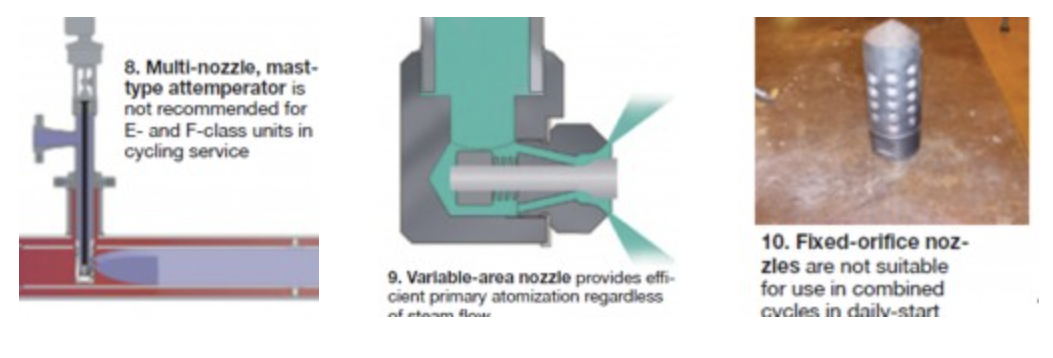
Variable-area probe-style attemperators were a popular choice for low- to medium-flow applications (and sometimes still are) when orders for plants powered by gas turbines surged in the late 1990s (Fig 8). On paper, these desuperheaters having spray-water control-valve trim in the steam flow stream, offered excellent turndown by virtue of their numerous spray nozzles, Anderson said. But cycling and the high steam temperatures associated with F-class engines, in particular, caused bending and cracking of the probes (a/k/a masts) in many units, rendering the desuperheaters useless.
Anderson showed cutaway drawings of a few other attemperators of the multi-port mast type, some designs quite involved, but all with serious limitations in cycling service. One supplier of reheater attemperators thought it could mitigate bending and cracking of long masts—generally attributed to bending moments created by the flow of steam and to flow-induced vibration—by shortening the masts to less than half the diameter of pipes they were installed in. The short-mast idea didn’t work as planned: The spray pattern was ineffective.
Anderson said that best attemperation results in E- and F-class combined cycles, based on his experience, are being achieved by variable-area spring-loaded spray nozzles (Fig 9). Fixed-orifice nozzles are not suitable for this service, in his opinion (Fig 10). The variable-area nozzles can be used in mast-type systems providing the moving parts of the control valve are located outside the pipe (Fig 11). Several attemperator manufacturers have adopted this concept with satisfactory results.
An alternative is the ring-style attemperator which admits spray water normal to the flow of steam (Fig 12), thereby offering better secondary atomization than the mast type, which sprays in the direction of steam flow. The ring design also ensures distribution of spray flow across the entire cross section of steam flow.

Atomization basics. Proper atomization and evaporation of the spray water supplied by an attemperation system is necessary both for good temperature control and to prevent water carryover. Complete assimilation of injected water into superheated steam involves three steps: primary and secondary atomization, and evaporation.
Primary atomization is the break-up of water into droplets by the attemperator’s nozzles. Goal is to create as small a droplet as possible regardless of the water spray flow rate. Variable-area nozzles offer this capability, fixed-orifice nozzles do not. Secondary atomization refers to the break-up of large droplets by the dynamic force of the steam flow. But for secondary atomization to occur, the dynamic forces acting on a droplet must be greater than the viscous forces holding the droplet together and depends on the relative velocity between the steam and water droplet. This objective is maximized by the ring-type attemperator.
Finally, the small droplets produced by secondary atomization boil and evaporate. The time to achieve complete evaporation depends on the total surface area of the water injected and is proportional to the square of the droplet diameter. Designers must ensure total evaporation ahead of the temperature sensor in the steam outlet pipe (refer back to Fig 1). Wetting of the sensor would make it virtually impossible to control steam temperature as intended.
Attemperation system design. In addition to specifying that the spray-water flow-control element be located outside the hot steam environment, engineers at Control Components Inc, Rancho Santa Margarita, Calif, suggest adding a thermal barrier to separate the hot and cold working elements to mitigate the intensity of thermal cycles experienced by critical components (Fig 13).

A proper liner is an important element in every desuperheating station. In addition to protecting steam piping against thermal shock, it increases steam velocity to improve secondary atomization, creates vortices that improve atomization and enhance mixing, and assist with heat transfer and evaporation. CCI has done considerable research to ensure complete evaporation of spray water and predictable performance to avoid damage experienced by many owner/operators. Fig 14 presents the details.
Anderson offered a simpler approach: The “Rule of Five Up and Twenty Down”—that is, a straight run of pipe ahead of the spray nozzles equivalent to the total length of five pipe diameters and a straight run of pipe equivalent to 20 pipe diameters downstream. He said that use of a ring-style attemperator might reduce the downstream straight run by the equivalent of a few pipe diameters.
A follow-on article will help plant personnel troubleshoot attemperators using DCS data and to specify an effective controls arrangement to mitigate problems faced by many users. CCJ


