


Protect underground piping from corrosion: What to do before the outage
By Jerry Weiser, Norton Corrosion Ltd
You look at your calendar and see that you have 180 days before your planned outage. Looking out the window to where your plant’s fuel lines meet those from the gas transmission and supply system, you are concerned about corrosion, and have to make unscheduled repairs. You want to solve these issues. You also want to make sure your good piping remains that way.
First, identify the pipes you are most concerned about in order of importance. Safety, of course, is top priority. Safety of your staff, your assets, and the community you work in. The pipes that usually stand out with respect to safety and plant operations are fuel gas piping, fuel oil, other volatile gas piping, water and fire hose lines, oil/water drainage, and water drainage.
Corrosion basics
Next, understand the three most common types of corrosion mechanisms that affect buried pipe. Bimetallic corrosion is the most common type found in power stations (Fig 1). It is an electrochemical process that takes place when these three conditions exist:
- Two metals with different amounts of “stored energy” are present.
- The two metals are electrically connected.
- The two metals sit in a common electrolyte (solution), such as soil or water.

With respect to stored energy (potential energy), think of the amount of energy that goes into producing one metal over another, say steel and copper. More energy is used to make steel than softer copper. Also, note that there is more potential energy in new metals than the same, but older, metals that have been “ageing” in the ground for several years.
Electrical connections are present when dissimilar metals are bolted together at flanges or welded. Unplanned connections occur when pipes contact a pipe support or piece of rebar, for example.When all three conditions are met, the bimetallic corrosion process seeks to establish electrical equilibrium between the different amounts of stored energy in the two metals. Excess energy contained in the steel flows through the soil or water to the copper. This direct current (dc) flow is just like that in your flashlight’s battery.
Every unit of energy that leaves the steel also removes a small amount of metal from the steel. When this happens repeatedly in the same place on your pipe, the pipe will develop large “corrosion pits” that penetrate the pipe’s wall thickness, and the pipe begins to leak.
Exposure corrosion (Fig 2) is the second type of corrosion often seen in power stations. When a pipe’s coating is damaged, such as when a shovel or backhoe hits buried pipe accidentally, it creates a path of least resistance for the flow of corrosion-related currents.
In addition, corrosion grows underneath the coating that is present. The coating will lift away, exposing more piping surface to corrosive action. This process is called exposure or coating holiday corrosion.
 Stray-current corrosion is the third most common corrosion process in powerplants. It takes place when electrical current that is not intended to be present on your piping leaves the pipe’s surface. For a real world example, consider a dc-powered trolley. The current is designed to return to the power source along the rails on which the trolley rides. A broken weld connecting two rails, or a missing wire that electrically connects two rails, compromises the intended path of the current.
With the trolley’s dc current “return path” compromised, the poorly coated large-diameter steel water line directly under the rails becomes the path of least resistance for the trolley’s return current. When the current “jumps off” the water line to return to the dc power source, current leaves the water line. Every unit of energy leaving the steel removes a tiny piece of steel from the steel.
The stray-current corrosion process can develop the same type of “corrosion pits” as the bimetallic corrosion process, with the same result: A leaking pipe when the pits penetrate the pipe’s wall thickness.
Consider your options
Understanding the basics pipe corrosion at generating stations allows you to make choices about how to solve your corrosion concerns. Doing nothing is a valid choice when the piping is slated for replacement or decommissioning.
A second choice is to consider using nonmetallic piping to replace a section of buried pipe that is prone to corrosion. If you consider pipe replacement during your outage, will nonmetallic materials stand-up to the heat, pressure, or other demands caused by how you are using the pipe?

A third choice is to alter the environment around the piping. This can be done by locating the pipe above ground (removing the soil that surrounds the pipe and exposing it to air), or placing lower resistance soil around the pipe to allow cathodic protection (CP) current to flow more readily onto the pipe from existing CP systems.
A fourth choice is to change the resistance of the corrosion (dc) circuit by repairing damaged original coatings, or installing new replacement pipe sections that are coated. Installing isolation flanges reduces the size of the area impacted by corrosion, eliminates possible stray-current corrosion concerns, and alters the corrosion (dc) circuit.
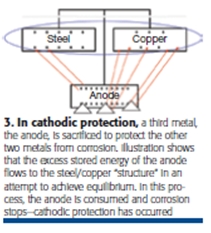
Adding cathodic protection (CP) to your piping is another choice to prevent corrosion. CP adds a third metal (anodes) with more stored energy than the bimetallic circuit that is causing corrosion to occur (Fig 3). Because the stored energy in the anode wants to be in equilibrium with the stored energy in the bimetallic corrosion cell, its excess energy flows from the anode to the latter.
When the anode loses energy, it also loses metal, and the anode corrodes instead of the pipe to which it is connected. Anode replacement—which is done perhaps every three, five, 10, or 20 years—is a much less expensive and predictable repair cost than pipe replacement.

The dc current that flows from the anode to the pipe collects on the pipe, and the current that collects on the pipe stops the corrosion process. When current is collecting on the pipe, it can’t leave the pipe. Stopping current flow from the pipe also stops metal loss from the pipe. When you stop the electrical portion of the electrochemical corrosion process, you also stop the chemical portion of the process, which is metal loss—or corrosion (Fig 3).
It’s 170 days to your outage. Depending on your background and experience, you may want to get assistance from in-house corrosion engineers, or outside experts, to help make the best choices.Proceeding with CP? What’s next?If CP is your solution of choice, you will need to get some information to your in-house or outside corrosion experts, including: which pipes you want to protect, soil resistivity (or water if piping travels under a lake or crosses a river), length and diameter of the buried pipe, details about the quality of the buried pipe’s coating, presence and location of electrical isolation, and dimensioned drawing of the pipes and layout. If this information is not available, the corrosion engineers may have to conduct a site survey.
You should expect a “Basis of Design with Design Calculations” report from the corrosion expert. The report should include type of CP system required, how easily current will flow through your soil or water, and the amount of electrical current required to protect your pipes.
The report also should include a complete bill of materials with the types and quantities of anodes, test stations needed to monitor the protective current, and miscellaneous wiring, connectors, and installation tools required to complete the project.
It is now 90 days before your outage begins.CP design detailsBased on his or her findings, your corrosion engineer may determine that burying magnesium ribbon along the length of your pipe is the best way to protect it. Multiple ribbons may be required in high-resistance soils, or if your buried pipe rests in a common trench with pipes owned by others.
Magnesium also is available as pre-packaged anode assemblies with ingots of the size specified by your engineer and include a lead wire factory-connected to the anode’s core. This system is surrounded by a densely packed backfill of 75% hydrated gypsum, 20% bentonite, and 5% sodium sulfate. Note that THHN-insulated lead wires are not acceptable for direct burial. However, RHW-insulated or HMW/PE-insulated are acceptable for direct burial without conduit.

Test stations monitor CP potentials, or the amount of current collecting on your piping to keep them from corroding (Fig 4). You should annually monitor the current that collects on your pipes to confirm they are adequately protected. If test results are negative, your report should indicate which anodes must be replaced, and electrically isolate the piping (Fig 5).Test stations can be post- or flush-mounted, or mounted junction-box style. The post-mounted test station wiring connections shown allow more accurate “make or break” circuit testing, tested at lower cost when anodes are not directly connected to your buried pipes.
In non-powered CP systems using magnesium anodes, electrical isolation of the buried piping is very important, as achieved with the installation of isolation flange kits shown in Figs 5 and 6. Other devices needed to maintain electrical isolation are polarization cell replacement (PCR) devices, as well as link seals, and casing spacers.PCR devices provide operational safety to personnel during a lightning strike or other fault conditions. They maintain electrical isolation during normal operating conditions, eliminating electrical connections between your power generating station’s piping and the gas supplier’s during normal operating conditions while allowing fault currents to go to ground.
Link seals isolate piping passing through a wall, casing spacers isolate piping inside a casing at a road crossing, and Handy Caps® are used above ground to protect CP connections to your pipe from weather, or below ground to protect CP connections from dirt.
Final steps
It is now 75 days from the beginning of your outage. These are the only items that should be left on your task list before installing CP:
- Order all materials identified in the bill of materials from the corrosion engineer’s report.n Arrange for supervision of plant personnel doing the installation work, or make arrangements for contract installation work.
- Arrange for backhoe and other equipment to be available, if self-installing.
- Secure required permits for site “hot work” and lockout/tagout authorizations.
- Arrange for an in-house or outside corrosion expert (most often the same person who prepared your design) to perform post-installation acceptance testing of your new CP installation.
Everything is now in place; your outage begins in 15 days. ccj