


Steam-drum nozzle cracks, FAC, attemperator overspray top user concerns
When it comes to training plant personnel to operate and maintain heat-recovery steam generators (HRSGs), perhaps no organization is better equipped to handle the assignment than HRST Inc, Eden Prairie, Minn. The company conducts its HRSG Academy twice annually and always plays to a full house.HRST’s staff of more than two dozen engineers and technology experts spends the lion’s share of its time inspecting boilers, solving problems in the field, and managing repair work. There’s little having to do with HRSGs that someone in the company hasn’t seen.
So, when it came time to develop the program for HRST’s annual half-day special session at the 7F Users Group’s 2011 meeting in May, engineers focused on three areas of greatest concern to users today: steam-drum nozzle cracks, flow-accelerated corrosion (FAC), and attemperator overspray.
Steam-drum nozzle cracks
The 7F users attending the workshop were well aware of the need to inspect gas-turbine compressor airfoils and hot-gas-path components for cracking. Some also were familiar with tube cracking in the vicinity of superheater and reheater header joints caused by attemperator issues. However, relatively few seemed to know they also should inspect their steam drums for nozzle cracking.
Bryan Craig, PE, who conducted this portion of the program, told that group that HP steam-drum nozzle cracks are caused primarily by thermal stresses associated with fast startups, fast ramping, rapid load reduction, and spin cooling; pipe loads create additional stresses. Nozzles heat and cool more quickly than the drum shell, he reminded, and cracks usually initiate on the inside of the drum.Such cracking typically is identified with HRSGs behind F- and G-class gas turbines in cycling service.
Most problems have been in downcomer nozzles, but cracks also have been found in riser and other drum nozzles.The allowable temperature ramp rate for your HRSGs, the boiler expert continued, depends on the thicknesses of drum and nozzle walls. But that not the only thing, he said. Nozzle weld type—for example, set-on versus pass-through, full penetration versus partial—has a major impact as well.
And don’t forget weld details: Sharp inside corners concentrate stress. See “Review basics of tube-to-header joints,” to dig deeper. Access at www.ccj-online.com, click “Archives,” click “Summer 2004.”Where to look. For pass-through downcomers and other nozzle welds easily seen from inside the drum (Figs 1, 2), Craig suggested visual inspection followed by a mag-particle or dye-penetrant check. If you find any indications, he said, also check nozzle welds from the drum exterior.
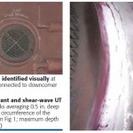 Use volumetric NDE—such as phased-array UT, shear-wave UT, and radiography—to determine crack depth.Set-on downcomer nozzles with welds outside of the drum should be inspected (visual and nondestructive examination) from the drum exterior.
Cautions. Visual inspection by itself is not sufficient for decision-making. Some cracks cannot be seen and some visual indications are not cracks, Craig said. Of importance to owner/operators is that crack propagation is not linear. The boiler expert noted that a 0.5-in.-deep crack in a five-year-old HRSG could be 1 in. deep in six months. He closed this portion of the presentation with an obvious reminder, “You can’t find cracks if you don’t check!”
If you find cracks be sure to determine the root cause. You don’t want to invest in repairs before knowing what caused the damage; a re-engineering effort may be required to prevent a recurrence.
Craig then spent perhaps 10 minutes discussing crack repair, defect removal procedures, codes governing repairs, NDE, surface preparation, pre- and post-weld heat treatment, welding electrodes, etc.The session provided attendees a deep appreciation for the complexity of pressure-part repairs. It also suggested that the inspection team you hire should be part of, or linked to, an organization with boiler design and repair experience.
Craig’s final recommendation: Avoid spin cooling.
FAC: What’s new? Nothing!
Then why do HRSG pressure parts continue to fail because of FAC attack? Some possible reasons are the following:
- Plant owners resist paying a relatively small premium to upgrade materials in sections of their new boilers that are prone to flow-accelerated corrosion.
- Boiler designers ignore high water velocities in susceptible areas.
- Experienced water chemists are greatly undervalued by plant owners.
- Plant personnel do not have adequate training in the basics of water chemistry.
- There is a temptation for overworked and under-supported plant managers to turn over responsibility for the health of their HRSGs to suppliers of water treatment chemicals.
Amy Sieben, PE, presented on the challenges of flow-accelerated corrosion. She began by explaining that the metal wastage characteristic of FAC is caused by a combination of chemical and mechanical processes that dissolve and/or strip away the protective oxide layer on the waterside of boiler components. A new protective layer forms and that, too, is removed. The process repeats until the metal is consumed.
HRSG design and water chemistry impact the rate of wear, she said (access “FAC and cavitation: Identification, assessment, monitoring, prevention,” CCJ, Spring 2004). Regarding design, the higher the fluid velocity, or the greater the fluid’s turbulence, the faster FAC proceeds. Damage typically occurs at fluid temperatures between about 200F and 500F, but is greatest at 300F. Carbon steel wears much more quickly than low-chrome alloys (P/T11 and 22).
The major chemical contributors, Sieben continued, are (1) pH levels below 9.4 and (2) less than 5 ppb oxygen in water and/or the presence of a reducing agent. However, zero oxygen and the use of a scavenger often is required where copper alloys are used in the condensate/feedwater system. Iron-dispersing polymers also have been linked to higher wear rates in some systems.
The most susceptible areas, Sieben told the group, are LP and IP evaporators operating at less than 400 psig and all economizers where the water temperature is near 300F. She then ran through a group of slides showing exactly where to look for FAC and how to recognize it (Figs 3, 4).
Thumbnail sketches of five case histories were next and a valuable part of the lesson. In the first example, FAC was identified after only four years of service. The gremlin, engineers found through rigorous analysis, was high water velocity at the exit of the jumper pipes in HP economizer harps.
Tube thinning occurred at the ends of about a half dozen tubes closest to the jumpers (Fig 5). Correction was to replace header sections and tube stubs in the affected areas with P22 material (Fig 6). This type of work is done regularly so there’s a wealth of industry experience (access “Module, header replacement,” CCJ, 1Q/2008).

A second case history was similar, but the attack occurred in the LP economizer (Fig 7). Once again, headers and tube stubs were replaced with P22 and the headers were redesigned to incorporate internal flow baffling to minimize flow impingement.
Another case study revealed holes in LP evaporator risers because of high velocity (Fig 8). Recommendation was to replace all 78 carbon-steel risers in the HRSG with ones of low-chrome material and to commission an FAC risk assessment to prioritize further thickness testing.
Perhaps the most interesting case history involved a finding of severe upper LP evaporator header thinning (including holes). Inspection revealed insufficient baffling, which allowed gas bypass, which increased the rate of heat transfer, which raised the velocity of the steam/water mixture exiting the tubes (Fig 9). The stick-through tube/header connection helped to concentrate an impingement area at the top of the header (Fig 10).
Sieben closed by stressing that inspections can be expensive if you don’t “work smart.” Inspection and UT testing of the common risk areas is hard work and time consuming, she said. Installing scaffolding, removing gas baffles and insulation, cutting borescope openings, etc, eats up the maintenance dollar quickly. An FAC risk assessment, Sieben added, pitching one of HRST’s many services, can show you exactly where to look and how often, and what mods to make when to avoid forced outages.
Overspray puts high-energy piping at risk
After listening to Sieben, many workshop attendees had to think that scheduling inspections of their attemperators, and the piping immediately downstream from them, deserved priority status. She believes many plants have never inspected their desuperheaters and don’t know what might be going on under all that insulation. In one instance, pipe cracking went unnoticed until a roving operator saw steam coming out from under the insulation.
Sieben has knowledge of eight units where the piping downstream of both the HP and hot reheat (HRH) attemperators have been replaced because of extensive damage (Figs 11, 12). More specifically, the first five welds downstream of the HP desuperheaters (a circumferential pipe weld and four more on the two 90-deg elbows) all were cracked.
Inspection using the phased-array ultrasonic method identified another eight units with pronounced cracks that HRST engineers and metallurgists are now studying. They are help clients plan replacements.
The boiler designer thinks there may be as many as 30 to 50 generating units in the country with serious attemperator issues. One unit, she said, has replaced desuperheater downstream piping twice in five years. After the first failure, the plant was led to believe that the problem was rooted in orientation and atomization. But that proved incorrect: The problem was overspray, as it often is with F-class equipment.

Sieben took out her picture book to illustrate that excess water wreaks havoc with everything downstream of the desuperheater, especially when overspray occurs for prolonged periods and it cools the pipe to the extent that it is not contributing to evaporation at all. She and her colleagues have seen cracking in straight pipe, in the weld seams and base metal of elbows, and in superheater tubes where rapid cooling caused tubes to separate from the header. Figs 13 and 14 attest to the severity of damage experienced.
Phased array is Sieben’s preferred inspection tool. However, she warned, the ability to identify cracks depends significantly on the quality of the contractor doing the work. X-ray is Sieben’s second choice—conventional or computed topography (digital x-ray). Regarding the latter, setup is expensive but you get fast results with minimal radiation.
She suggested that any plant overspraying should inspect at the next outage. If cracking is found, Sieben suggested planning for replacement piping immediately. Crack propagation is non-linear, she reminded, and it’s virtually impossible to predict when failure will occur.
Desuperheaters have been the subject of several articles in the COMBINED CYCLE Journal over the years. They offer best practices regarding where and how desuperheaters should be installed to minimize wear and tear on downstream piping. Access “Avoid desuperheater problems with quality equipment, proper installation, tighter control, Fall 2004; “Tight specs, good engineering, quality manufacture ensure reliable control of steam temperature,” 1Q/2005. ccj