


Heat-recovery steam generators (HRSGs) and the associated selective catalytic reduction (SCR) units often take a back seat to gas and steam turbines at combined-cycle facilities. That was not the case at the Combined Cycle Users Group (CCUG, www.ccusers.org) conference in San Antonio, Aug 22-25, 2016.
Several users shared their experiences on HRSG and SCR O&M issues arising from cycling and low-load operation. Vendor and consultant experts added to the general bank of knowledge around performance, diagnostics, condition assessments, and engineering solutions. Registered users can access these informative presentations on the PowerUsers website at www.powerusers.org.
What price low-load operation?
Not surprisingly, the need to address performance issues during cycling, low-load, and start/stop operating regimes dominated mind share at the conference. After all, being flexible, adaptable, and resilient are the watchwords in the industry today.
Bryan Craig, PE, HRST Inc’s director of engineering, reviewed the following HRSG risks during low-load operation:
- Economizer flow instability.
- High superheater and reheater metal temperatures.
- Partial operation of 2 × 1, 3 × 1, and 4 × 1 plants—that is, when not all of the gas-turbine (GT)/HRSG strings are in operation.
- Attemperator overspray.
- Catalyst temperature.
- Oxidation of non-pressure-part components.
With respect to the first risk, the example Craig cited was compelling: An HRSG unit of a 2 × 1 facility operated 18 years at baseload (down to 60% GT capacity) with no economizer tube leaks, then experienced multiple tube leaks after three years of cyclic operation during which the unit was frequently turned down to 45% of GT capacity.
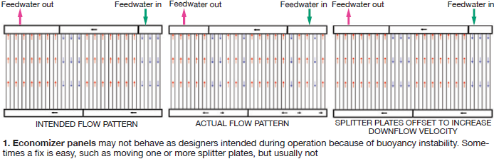
What happens under these conditions is called buoyancy instability—when the downward velocity (most panel-type economizers have a few tubes with downward flow) is too low, and buoyancy of warm water causes flow instability, reducing heat transfer.
Stagnant and reverse-flow tubes become hotter than neighboring tubes, leading to tube thermal stress. Perhaps the greatest consequence is that leaks can occur at tube-to-header welds which are difficult to access for field repair.
Possible solutions include eliminating the down-flow tubes, increasing flow velocities, or reducing stress at weak areas. To increase velocities, the economizer splitter plates can be repositioned to achieve more down flow than up flow, but this also increases risk of flow accelerated corrosion (FAC) unless done properly (Fig 1).
Superheater and reheater tube metal temperatures can increase and cause problems during extended low load, unfired (duct burner) operation (when temperatures in the first HRSG module are often at their highest) and when the GT is operating at low load. In the latter situation, the exhaust temperature for many GTs is at its highest. Because the attemperator is keeping the steam temperature constant inside the tube, the differential between outer and inner surface temperatures increases as GT exhaust gas temperature increases.
This creates what Craig called a “vicious cycle” inside the tube. Internal oxide growth increases, slowing heat transfer further, and increasing tube temperatures more. High metal temperatures reduce creep strength; reduced wall thickness increases tube stress. Combined, they can shorten tube life considerably.
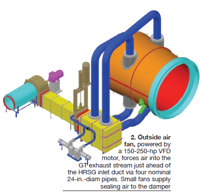
When you add the attemperation effects, the problem gets complex in a hurry. HRST has solved problems like these through a combination of superheater and reheater tube shields and/or installation of its trademarked Quenchmaster air attemperation system (Fig 2). However, the potential impact on performance (heat rate, capacity) should be considered.
Steam separation in the HRSG steam drum is aggravated with one or more GTs not running in a multi-GT facility. The steam turbine is a constant volume machine, notes Craig, so running one unit of a 2 × 1 plant approximately doubles the velocity through the steam separator, and running one unit of a 4 ×1 plant about quadruples it (if the steam turbine isn’t throttled back).
Steam separation equipment must be designed for the worst-case conditions. If not, reheater drains and cold-reheat piping should have automated condensate detection and removal; reheaters of offline HRSGs should be equipped for isolation; and the units should be assessed for uneven cold reheat flow distribution which can lead to high metal temperatures in units receiving less flow.
Ecomax™ for HRSGs
EthosEnergy Group’s Bill Barras and Chris Chandler discussed how the popular tuning system for GTs is being expanded to include HRSG optimization. Chandler, whom Barras described as the person who “built” Ecomax, said, “this product is for HRSGs with attemperation problems.” Essence of the new capability: The software “integrates HRSG pinch points, relative to tuning, directly within the control of the gas turbine fuel/air ratios.”
Ecomax is a software tool which optimizes performance in real time, rather than at one or two discrete periods during the year. Among other things, it allows a unit to be “self-tuned” after a combustor, hot-gas-path, or major inspection. Barras reminded the audience that the software is not model-based; it uses live real-time data. It pursues one theme at a time—for example, minimum NOx emissions.
The reported primary benefit of the new feature is the unit can more easily remain in compliance with NOx emissions limits at part load while avoiding common HRSG thermal issues experienced under reduced gas flow and higher turbine exhaust temperatures. The expected turndown improvement is about 10%—subject, of course, to site-specific conditions. Barras noted further that Ethos monitors 70 units for its customers from a remote M&D center. “Steam turbine optimization is coming next year,” he added.
Twice-daily cycling
If you think you’re cycling a lot now, maybe you haven’t seen anything yet. At least, that was the implicit message of one user representing multiple plants for which the owner is actively planning for an operating regime characterized by two starts per day. The CC units essentially were designed for baseload operation 10 years ago. Like most facilities facing such scenarios, these operate in a wind/solar intensive region.
While there are many O&M, compliance, performance, and budgeting issues associated with such a change, an important consequence is that critical HRSG components—such as attemperators—will wear out twice as fast (as if attemperators weren’t already enough of a problem). In general, a thorough evaluation by the owner/operator concluded that more HRSG tubes, as well as critical valve and pump parts, should be stocked. These same components would require more frequent maintenance to avoid impacts on plant and system reliability.
Although the budgeting is still a work in progress, the initial assessment shows that balance-of-plant maintenance for twice-daily cycling would increase by $2.50 to 4.00/MWh. Here, BOP includes everything except the gas and steam turbines and their respective auxiliary skids
More frequent drum weld inspections
Another consequence of twice-daily cycling, and more frequent on/off cycling generally, is likely more numerous steam-drum weld cracks. A diagram shown in a second presentation by HRST, this one by Lester Stanley, explains why: Going from 0 to 400-psig steam pressure creates the greatest and fastest temperature differential in steam saturation temperature (Fig 3).
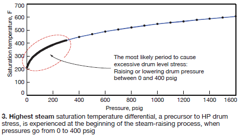
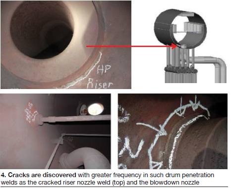
Thermal stresses, in turn, lead to higher stress on the HP drum nozzle and shell welds (Fig 4), especially when pass-through partial-penetration welds are used.
The balance of Stanley’s presentation reviewed planning strategy for inspections, several effective inspection techniques—including visual inspection (by someone who knows what they are looking for), phased-array ultrasonic testing, and magnetic-particle inspection.
Stanley advocates applying the joint API (American Petroleum Institute)/ASME standard API 579/ASME FFS-1, for “fitness for service,” developed to “make informed decisions about defects found in-service during inspections.” When conducting repairs, don’t neglect any opportunity to improve the weld procedure and avoid weld repairs which may lead to additional stresses.
SCR impacts
Low-load operation leads to changes in temperature, mass flow, and mixing characteristics in SCRs. Andy Toback, Environex Inc, reviewed several items to be considered for maintaining compliance. They include, for startups:
- Expect an increase in catalyst activity with higher temperature.
- Requirements for dilution air temperature in the ammonia delivery system may change.
- Modifying the SCR system control logic may help you comply with stack emissions earlier in the startup cycle.
For low load operation, Toback recommends:
- Analyzing operating data to determine catalyst performance requirements at each load condition
- Testing catalyst condition, along with operating data, to project remaining life – low load operation may shave a year or more off of the catalyst life.
If the operating profile is expected to be the same for many years (although who can forecast that), consider adjusting the catalyst formulation when it comes time for replacement. The ideal temperature for an SCR catalyst is 700F, notes Toback, but adjusting the formulation can extend performance from 400F to 1000F.
A bird, a plane. . .a drone
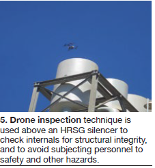 Drones are getting more attention these days, although most of the material seems to focus on understanding the bewildering matrix of federal, state, and local rules and regulations restricting their use. They are being considered more often for getting a peek at areas which are impossible, difficult, or just plain inconvenient to access (Fig 5).
One user at the CCUG meeting described experience with early application of drones for these purposes. Equipment listed as potential subjects for inspection are elevated structures, such as stacks, silencers, valves, and pipe racks; HRSG interior and exterior; cooling towers; and high-energy piping. In time, drones likely will be incorporated into regular preventive maintenance programs and activities, noted the presenter.
The user case detailed was inspection of a silencer for structural integrity of internal components, coating system integrity, and mechanical connections. Many of the potential advantages of drone use are obvious, but some worth mentioning include reducing exposure of crew to safety risks, avoiding scaffolding and/or crane costs, and the ability to manage the inspection at the plant level without corporate resources.
The chief limitation is that if anomalies are identified, they can only be addressed by conventional means. In other words, you’ll need scaffolding or crane or an elevated crew to do the repairs. The inspections are also limited, in this plant’s experience, to line-of-sight of the camera on the drone which is easily impaired by obstructions and poor lighting. There can be loss-of-signal issues around thick metal components, too.
Still, the conclusion here is that accelerated use of drones at power stations is inevitable. The technology is advancing rapidly. As long as the regulatory framework doesn’t inhibit the applications, drones are best considered another form of automated, labor-saving device, not unlike borescopes and other cameras used to inspect equipment internals. CCJ