


Uprate project boosts plant output by one-third
Challenge. More power was needed from Milford Power LLC, which began commercial operation in 1993 as a nominal 150-MW (90F day), W501D5-powered, 1 × 1 combined cycle equipped with an unfired heat-recovery steam generator and SCR catalyst for NOx control. The steam generated today powers a Siemens (ABB) SST-700 HP/VAX LP turbine. The generator coupled to the gas turbine is hydrogen-cooled, the generator serving the steam turbine is air-cooled.
Cycle cooling is by a surface condenser and four-cell wet cooling tower. Cycle makeup is produced by a system using reverse osmosis and continuous electrodeionization in series. Grey water from the local wastewater treatment plant provides makeup for the cooling tower.
 Solution. To increase output, the owner proposed modifying the as-built plant by adding a wet compression system at the gas-turbine (GT) air inlet and duct-firing capability to the HRSG, and upgrading the steam turbine.
Wet compression. When used in conjunction with the existing evaporative coolers, the wet-compression phase of the project increases GT output by 13 MW—when the ambient temperature is between 60F and 90F. Wet compression works by injecting demineralized water into GT inlet air to increase mass flow, hence gas-turbine output. Unit efficiency increases as well: A 10% boost in output is achieved with an 8.5% increase in heat input. Use of wet compression at Milford increases demin-water consumption by 80 gpm.
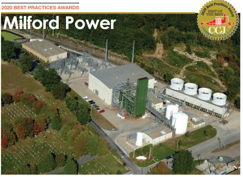
Equipment required for the wet-compression project included a spray-water delivery system (tubes and nozzles installed in the inlet air duct); a water transfer skid with pumps, piping, and controls (Fig 1); and interconnecting tubing between the skid and nozzle array. The nozzles are located downstream of the inlet silencers and are sized to achieve a uniform spray pattern and to prevent droplet formation to the degree possible. A drain line in the air inlet duct was increased to prevent accumulation of the additional water required. This drain was piped to a collection sump for use as cooling-tower makeup.
An observation window was installed on the inlet scroll, positioned opposite of the spray array to monitor the spray pattern.
Note that the wet-compression system does not increase pollutant emissions. Maximum emissions rates still occur at cold ambient temperatures (wintertime conditions) when wet compression does not operate.
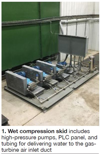
Duct burners added a nominal 500-million Btu/hr at the front end of the existing HRSG within an existing lined burner cavity (Figs 2 and 3). The seven new natural-gas burner assemblies, each equipped with pilot and flame scanner, doubles the HP steam flow to the turbine, thereby doubling electric production of the steamer.
Equipment added to support the duct-burner system, and the additional steam flow, included the following: new HP-superheater manifold piping; new trim for the HP steam and feedwater control valves; replacement of nine existing 1-in. HP-superheater drains with 2-in. valves; access platforms for each duct-burner assembly (one on each side of the HRSG), new fuel-gas piping, manifolds, and distribution skid; air blower for cooling air to the flame scanners; and a new compressed-air supply receiver for purge air.
 An air-flow model study was conducted by the HRSG OEM “to define the minimum air-flow distribution devices required to ensure acceptable velocity distributions at the entrance planes of the duct burner, and to determine from model measurements the change in the system pressure loss due to the installation of flow-distribution devices.” This modeling guided modification of the HRSG exhaust-gas inlet distribution grid: Half of the holes in the lower 8 ft of the perforated plate were covered to redirect a larger volume of air flow upward.
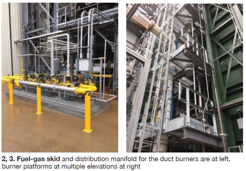
The existing SCR catalyst was replaced with a multi-function catalyst to control emissions of NOx, CO, and VOCs in accordance with proposed limits of 2 ppm for NOx, CO, and ammonia slip (Fig 4). The new catalyst combines the catalytic function of SCR NOx reduction and CO/VOC oxidation into a single catalyst layer.
Note that use of the duct burner is limited by the current ambient air plan to the heat-input equivalent of 2000 hr/yr. The pressure drop across the catalyst is 1.5 in. H2O.
The existing ammonia delivery system and injection grid were reused. The grid manifold and piping were vacuumed and the nozzle openings cleared of any blockages. With the existing catalyst removed, it became necessary to repair the upper support bracing and locking mechanisms used to secure the catalyst frames on the downstream side.
CEMS equipment and its companion data acquisition system were reused, but reprogrammed to address the new lower emissions limits and air-permit obligations.
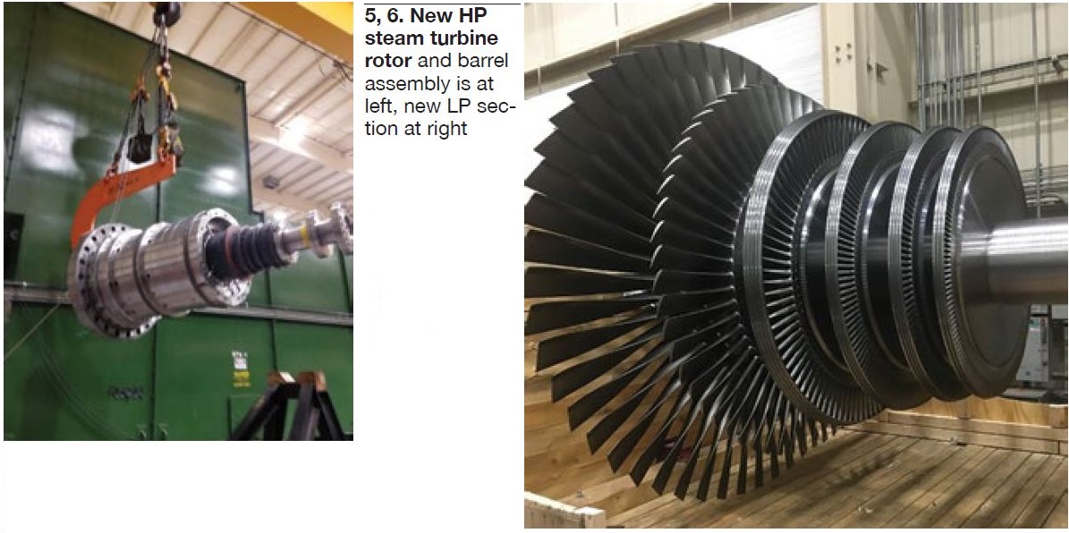
The steam turbine was uprated to 93 MW from 42. The new HP cylinder features a more robust blade-path design using the existing casing and inlet control valves to address the higher steam flow (Fig 5). The new LP turbine also was designed with a robust blade path, as well as other improvements (Fig 6).
The original mechanical overspeed trip was disabled and a new hydraulic trip block with speed probes to support integration of the replacement electronic trip system within the Emerson DCS was installed. Additional monitoring and performance measurement instrumentation was added to both the HP and LP turbines in support of the project’s final testing.
Steam admission and extraction valves were disassembled and inspected, with some suggested OEM service-bulletin betterments applied. The HP casing was inspected where indications were found in the area of the HP inner gland and valve seat areas. These were removed as recommended by the OEM with no further corrective action.
New thrust-bearing shoes and liners were installed along with the inspection and reuse of existing journal bearings. An internal alignment of the new LP diaphragms required elevation changes to both the diaphragms and bearing pedestals.
Miscellaneous notes. Milford Power was designed as a 2 × 1 combined cycle, but the second GT was never installed. Thus, the existing generators for the steam and gas turbines were sized accordingly. The reduction-gear assembly between the HP turbine and generator was inspected and confirmed as suitable for the increased loading.
Existing step-up transformers, surface condenser, condensate pumps, circulating-water pumps, and cooling tower also were adequate for the uprate. While more demineralized water, and grey- water makeup to the cooling tower, were needed to implement the uprate, no changes to the existing treatment systems were required.
The additional control requirements dictated changes to the DCS. However, the PLCs for the wet-compression and duct-burner systems were connected to the DCS to provide status only; control of both systems remained with their respective PLCs.
Results. The uprate modifications were located within the existing infrastructure of the facility and increased plant output by approximately 53 MW. Some of the takeaways and lessons learned from the project are summarized below:
- The overall project took four years to complete and involved three different owners.
- Operational information on the GT exhaust communicated by a former owner, although not completely accurate, was used as a basis for design of the upgrades. A new GT exhaust NOx analyzer was installed to better define emissions values at the different load ranges.
- Local building permits were required, making it necessary to work with town employees most familiar with occupational type buildings and not utility facilities.
- On projects like this, it is important to have an effective cost-management program in place for time-and-materials type contracts and emergent work discovered that is outside the base scope.
- Working with three different major contractors resulted in a fragmented project schedule. It took the effort of plant personnel to finalize an overall project schedule that clearly identified project milestones.
- Piping supports were pre-designed based on known pipe runs; field-run piping was not considered.
- The existing 50%-capacity boiler-feed pumps that each provided 100% of the plant’s capacity without duct burners now provide only 50% capacity with the burners in service. Thus, it is necessary to operate both pumps to achieve the higher output with no backup available.
- High noise levels from the fuel-gas skid for the duct burners was discussed in the planning process but no solution was provided for mitigation.
- Compressed air from the GT air inlet compressor extraction point now contains more moisture with wet compression in service than previously.
- Steam-turbine output was believed limited to 93 MW prior to operation; engineering review showed it was 96 MW based on steam conditions.
- Electrical/control drawings. A pre-review of available onsite drawings indicated they had to be updated to the actual configuration of the existing circuitry so the engineering contractor could issue correct field drawings for installation.
- A second flow model for ammonia flow from the AIG across the new catalyst should be done to better understand any inefficiencies. Also, operational flow measurements should be taken to validate the effectiveness of new catalyst.
Notable accomplishments:
- Experienced no OSHA recordable injuries, no lost-time accidents, no environmental events.
- Achieved an additional 13 MW with wet compression in service.
- Achieved the performance guarantee of 90-MW output from the steam turbine.
- Demonstrated 204-MW plant output to ISO New England.
Project participants: William Vogel, Chris Tea, Kris Buckman, Kevin Collins