Implement recommendations in 1509-R3, 1638, 1795 to reduce operational risks
Technical Information Letters (TILs), published periodically by GE Energy, offer recommendations to resolve equipment issues, improve gas-turbine O&M and reliability, and protect the health and safety of plant personnel. They should not be ignored or set aside for future consideration.
Unfortunately, TILs do not always filter down to responsible personnel on the deck plates; and even when they do, operators sometimes find the language confusing. Either way, the message may not get through to where it’s needed.
Perhaps no one sees the breakdown in communication as clearly as the field service personnel at Advanced Turbine Support Inspections LLC (ATS), Gainesville, Fla, who follow TIL requirements to the letter when making their periodic borescope inspections. The need for a better understanding of gas-turbine (GT) technical issues by the O&M staffs at plants powered by 7FAs prompted the development of a webinar focusing on the importance of TILs 1509-R3, 1638, and 1795 to owner/operators. The webinar, which aired December 14, provided the content for this report.
You may recognize some of the issues identified from previous articles, such as S0 vane cracks in “Keep up with OEM advisories,” which appeared in the 2011 Outage Handbook (access at www.ccj-online.com). But those articles typically focused on one or two specific concerns introduced in discussion sessions at user group meetings. This report summarizes the advisories of greatest importance to most 7FA owner/operators in one place, presents industry-wide inspection findings, and offers some suggestions from the inspection team based on field experience.
Mike Hoogsteden, Dustin Irlbeck, and Rod Shidler of ATS developed the material presented by Hoogsteden and Irlbeck on the webinar, CCJ ONscreen’s Scott Schwieger coordinated and produced the event, and Engineering Manager Greg Snyder represented sponsor Dresser-Rand LETT (sidebar).
1509-R3 highlights
- R0 leading-edge distress can be caused by impact damage, root-area erosion by fogging, and/or the introduction of corrosive elements into the compressor inlet. Cracks left unattended can grow to 1.5 to 3 in. before blade liberation and significant collateral damage. The TIL recommends annual visual inspection. If any R0 root cracks are identified, inspect all R0 roots immediately. ATS believes that the TIL doesn’t go far enough and has the potential to miss small or tight indications that could result in blade liberations and a catastrophic compressor event.
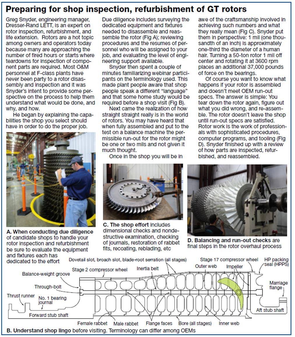
- R0 and R1 blade-tip distress is caused most commonly by tip rubs against the case during operation. This usually is identified by tip discoloration or a heat-affected zone (HAZ) or by rolled metal. Such distress can lead to radial tip cracks (Fig 1) and tip liberations with significant collateral damage to forward and aft compressor stages. If tip discoloration is identified, the TIL recommends dye penetrant inspection at 25, 50, and 100 actual fired starts from the discovery of the rub. If rolled metal or tip loss is identified, repairs should be completed at the first opportunity. Until then, dye pen inspections should be performed every 12 actual fired starts. After repairs, inspect at 25, 50, and 100 actual fired starts. ATS has identified multiple rotor-blade cracks with visible dye penetrant that were not seen during conventional visual inspections.
- S0 stator-vane trailing-edge cracks apparently are caused by vane “lock up” (Fig 2). Cracks could result in vane liberation and significant collateral damage to forward and aft compressor stages. If trailing-edge cracks are found, replace the affected vanes immediately. Note that ATS has identified S0 trailing-edge cracks with an eddy-current inspection that were too small to find visually and with fluorescent dye. Further, ATS has identified S0 leading-edge and radial tip cracks in both flared and unflared compressors; they are not addressed in 1509-R3.
To sum up, in the last 10 years ATS has completed more than 1000 in-situ inspections and identified over 150 cracked rotor blades, more than 60 S0 cracked vanes, and two S1 cracked vanes. For rotor blades and stator vanes that do not show any signs of distress, ATS recommends the following as a minimum: Annual visible dye-pen inspection of R0/R1 blades. Plus, dye-pen or eddy-current inspections of S0 vanes annually or after each 100 actual fired starts. Subsequent inspections based on the results of the inspections would run parallel to the OEM’s recommendations.
1638 highlights
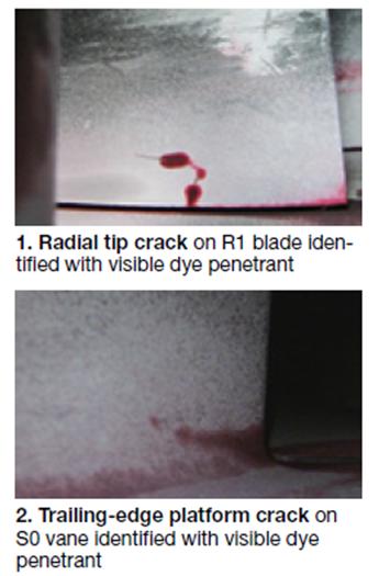
TIL 1638 addresses F-class R0 in-situ and R1 case-off ultrasonic inspections (UT) for dovetail distress below the blade platform. The testing interval is to be 8000 fired hours or 150 fired starts, whichever occurs first. This recommendation is modified for peaking units performing more than 150 annual starts to just before and following the peak season. The TIL applies to all Frame 7 and Frame 9 F-class turbines installed with non-undercut R0 blades (which includes the baseline standard R0 and P-cut R0 designs).
 The distress area generally is in the center fillet region on the suction side of the rotor blade. Additional distress areas identified during ATS inspection are the entire sloped face in the center fillet region on the suction side and both the leading- and trailing-edge regions on the pressure side (Figs 3 and 4). Here’s a rundown on ATS inspection results to date:
- Standard R0 blade suction-side fillet region: 41 cracked blades. Damage found at from 1600 to 58,000 fired hours and from 30 to 2700 starts.
- Standard R0 blade suction-side slope region: three cracked blades. Damage found at from 7600 to 33,700 fired hours and from 659 to 2059 starts.
- Standard R0 blade pressure-side fillet region: one cracked blade at leading edge, one at trailing edge. Damage found at from 7300 to 21,700 fired hours and from 888 to 1482 starts.
- R1 blade suction-side fillet region: two cracked blades (both in-situ). Damage found at from 9100 to 44,000 fired hours and from 255 to 655 starts.
To sum up, ATS has to date identified 116 dovetail cracks with no false calls. It also has found R0 dovetail cracks which are outside of the interest areas and coverage capabilities of other inspection agencies. Finally, the company’s inspection team has identified R1 dovetail cracks in-situwhich ranged from about 1 to 3 in. long and from depths of 0.255 to over 1 in. The cracks in this last unit likely would have propagated to failure before the next scheduled case-off accessibility.
ATS recommends performing ultrasonic inspections of the R0 and R1 platform areas before and after each peak operational season and not exceeding a six-month interval. Subsequent inspections are based on the results of the inspections and would run parallel to the OEM’s recommendations.
1795 highlights
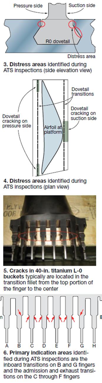
TIL 1795 pertains to L-0 40-in. titanium bucket inspections on steam turbines found in some F-class combined-cycle plants. It was issued in response to cracking identified in dovetail fingers of some buckets. Cracks typically are found in the transition fillet from the top portion of the finger to the center (Figs 5 and 6). At least one instance of bucket liberation has been reported (in Korea). Here are the OEM’s suggestions:
- Remove the last-stage buckets and perform a fluorescent penetrant inspection (FPI).
- Evaluate for inspection applicability units operating above 650 start/stop cycles, or those planning to run above 650 cycles prior to bucket modification.
- TIL should remain in effect until the L-0 buckets have been replaced with hardware of new design.
TIL 1795 is time-consuming to perform. Estimate four weeks just for conducting the inspection (breaker to breaker) if you’re going to use the OEM’s plan. Add another three weeks to modify the buckets as well. Alternatively, you can opt for ATS’s recently announced in-situ inspection technique, which requires one 12-hr shift per row with minimal unit downtime and preparation. Note that removal of the LP turbine hood, rotor, and buckets is required to conduct an FPI inspection.
Findings to date include the following:
- D11 steamer with about 1600 start/stop cycles. All L-0 buckets were inspected; all had cracks ranging in depth from 0.1 to 0.193 in. and from 0.064 to 0.531 in length.
- D11 steamer with about 1400 start/stop cycles. Inspected 41 of the 152 L-0 buckets (76 for each of the two L-0 wheels in the two-flow LP section) and found cracks in each ranging from 0.44 to 0.179 in. deep and 0.073 to 0.407 in. long.
- A10/D11 steam turbines with fewer than 1200 start/stop cycles. Ten L-0 rows were inspected in-situ with no recordable indications.
ATS recommends performing in situ inspections of the L-0 last-stage bucket dovetails yearly. End notes:
- In cases where many buckets are affected and spares are not readily available, an alternative to replacement is to machine off the L-0 buckets at the wheel OD and return the rotor to service (Fig 7). Output is reduced, of course—perhaps by 25 MW per wheel modified in this manner.
- For buckets having no indications, the holes for the retaining pins are reamed and oversize pins are used to reattach the airfoils to the wheel.