


By Engineering Staff, HRST Inc
The first five years of HRSG commissioning and operation are critical to establishing unit reliability and a satisfactory service life. In these early years, control and organization of supplier documentation will help to improve current and future decision-making. Inspections and analysis can help ward off potentially damaging conditions or identify items to allow contract closure with suppliers.
As time goes on, analysis also can determine the effects of any current or impending changes to operations that were not planned when original specifications were prepared. Finally, there are commissioning and early operating practices and conditions that can harm the HRSG. There are many examples, several provided below.
Year 1
Gather, organize, protect documentation. Managing maintenance or operations is not an easy task without complete and comprehensive documentation. The first step is to gather and organize the documents, confirming that all suppliers have submitted complete design packages. A reconciled list of documents with the latest revisions and dates is very helpful. Obtaining copies of the ASME Manufacturer’s Data Report forms can verify component design pressures and materials of construction, and aid in future repairs. Data reports can be purchased from the National Board of Boiler and Pressure Vessel Inspectors.
ASME B31.1 requires that every facility have an inspection program for covered piping systems (CPS). This primarily constitutes pipe 4 in. diam and greater between the HRSG and steam turbine or user. The program calls for a very comprehensive list of documents. A detailed list, as of the date of this publication, can be found in ASME B31.1, Article 141 under “Operation and Maintenance.”
With everything organized, it is wise to confirm that the documents themselves are complete. Look for drawings that say later or preliminary and have them replaced with the final revision. If as-built drawings are a contract requirement, be sure to pursue completion, particularly with piping and pipe supports.
The second step is to protect the documentation, keeping complete sets in multiple locations. Hurricanes can wipe them out in hours (that happened), and information collectors can pillage them slowly over the years (almost guaranteed to happen). Whether documents exist in electronic format or as physical manuals, or both, one set should be available for ongoing use and one set should remain protected and secured.
Inspection, testing, analysis
A pre-fire inspection is similar to a standard inspection but, because of construction and commissioning sequences, may be extended over a longer period. Documenting the conditions with abundant photographs will help answer future questions. This inspection should focus on design details, correct materials, and proper installation.
 Inspectors should go through the gas-side access and crawl spaces, paying close attention to the inlet duct and firing duct. Violent exhaust flow is known to take down components in the inlet duct if not installed properly. Note interferences from restrained thermal expansion of tube bundles and duct liner systems.
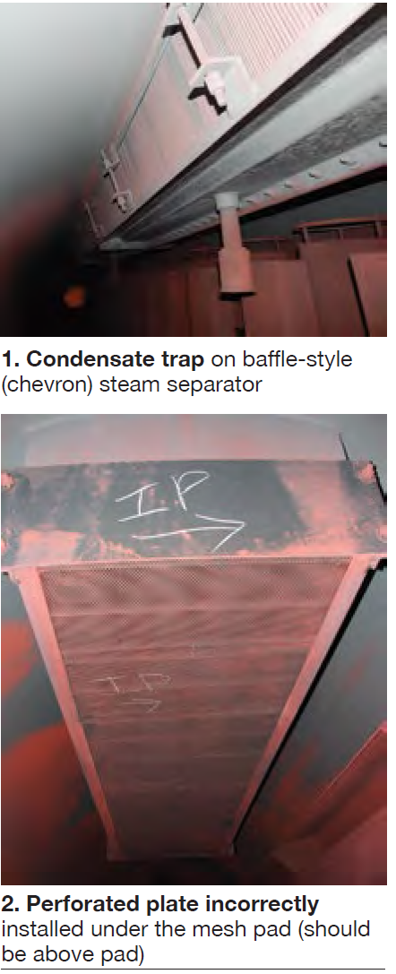
It is important to inspect each drum and pay close attention to the final (secondary) steam separator that covers the steam outlet to the superheater. It limits carryover of water droplets and impurities that can quench or plate out on downstream tube surfaces. Excessive carryover can lead to loss of superheat and elevated risk of tube damage from high temperatures. If enough water carries over, it can quench the tubes, causing fatigue damage at the header joints.
The final steam separator is typically an angled array of baffle plates or it may be a box filled with a mesh pad. For the baffle-plate style, a drain pipe should extend from the housing and either have a condensate trap or extend below the normal water level (Fig 1). This drain evacuates water from the casing while preventing steam from bypassing the baffles.
For separators that appear as a mesh pad in a box, the top and bottom typically have different mesh specifications. If installed upside down, the carryover will be higher than intended.
A more serious condition occurs when a perforated plate is placed on the bottom side of the mesh (Fig 2). The plate should be installed on the top of the mesh to boost the pressure drop through the separator, which evens out the steam flow through the mesh box, and lowers local velocities.
If installed on the bottom it does just the opposite. The orifice holes shoot high-velocity steam and water particles through the mesh, making it less effective and preventing any accumulated water from draining. The result is high carryover of water and impurities into the superheater.
All pipe and pipe supports external to the HRSG must be in the correct position and any hydro-stops removed before fired operation. This is a good time to document the hot and cold marks, before they fade or fall off. If low points in steam pipe cannot be drained, consult the OEM or contractor.
Some foundation base plates are intended to move as the duct expands. If so, the anchor bolt washers should be free to move if kicked.
Years 1 and 2
Post-fire inspection and testing. Near the end of the first year or just before expiration of warranty periods, post-fire inspection and testing will set excellent baselines for future inspections. By this time, hopefully, most operational kinks will have been worked out. Again, taking an ample number of photos allows comparison to pre-fire conditions, and provides clear references for future conditions.
 Within the gas path, inspectors should look for signs of restrained expansion, interferences, and wear. Some cracks and twists can be expected and are often self-limiting. Others are signs of imminent or future trouble. Improper material selection or the occasional installation of the wrong material will often be revealed as a difference in oxide color or scale formation. If damage is found, this is the time to address the mechanisms that will cause future component failures.
Typical problems include the following:
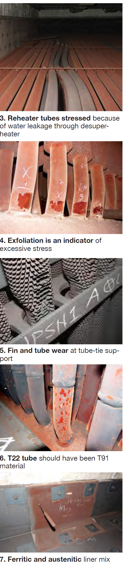
Stressed tubes. Warped tubes are not necessarily a liability, but they are signs that the tube has been stressed and has yielded (Fig 3). Additional fatigue may cause failure. Cracking might be apparent in tube joints. Stress is common in the superheaters, reheaters, and economizers (Fig 4). Failures have been known to occur shortly after commissioning.
External tube wear. Tubes are susceptible to oscillation from forced vibration caused by exhaust flow. A tube-tie support lattice typically is installed at multiple points along the height of the tube bank to limit this oscillation. If the tube ties are spaced too far apart or if they are loose, tube vibration causes fin wear, and eventually wear on the tube wall. Fig 5 was taken during a first post-fire inspection. It is wise to inspect tubes for signs of wear on the upstream and downstream sides of the first tube bank (as a minimum inspection).
Tubes should not be allowed to vibrate more than 0.125 in., assuming there are sufficient tube-tie restraints and that there is no sign of excessive or ongoing fin wear. Severe wear has been observed in early operations. Owners have contemplated removal and modification of tube panels to correct this issue or even purchased new panels if the wear exists on many tubes.
Overheated materials are those that have been subjected to a sufficiently high temperature for a length of time to cause changes in microstructure, or excessive scale formation (Fig 6). The materials are perhaps mismatched to the location in the HRSG.
In some cases, an entire group of components is mismatched, but more often, one or more individual pieces get mixed in with the correct materials. This is common almost exclusively to the inlet duct and firing duct (Fig 7). Inspectors may find one liner sheet, gas baffle, or tube that looks out of place. If not corrected, early failures can be expected.
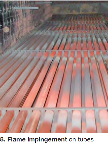 Duct burners. Look for signs of flame impingement on the walls or downstream tubes (Fig 8). Long flames or excessive localized heat can be caused by failed burner nozzles, inadequate fuel distribution, inadequate exhaust distribution, or improper controls.
Failure of one threaded burner nozzle can shoot flames far into the downstream tube bank.There could be hundreds of nozzles, and tube damage only requires one nozzle to fail. (One owner/operator looks for this condition by monitoring stack exhaust for elevated CO emissions.)
Online inspections. With the unit in operation, several checks can confirm both healthy and unhealthy conditions for some equipment, controls, and operations.
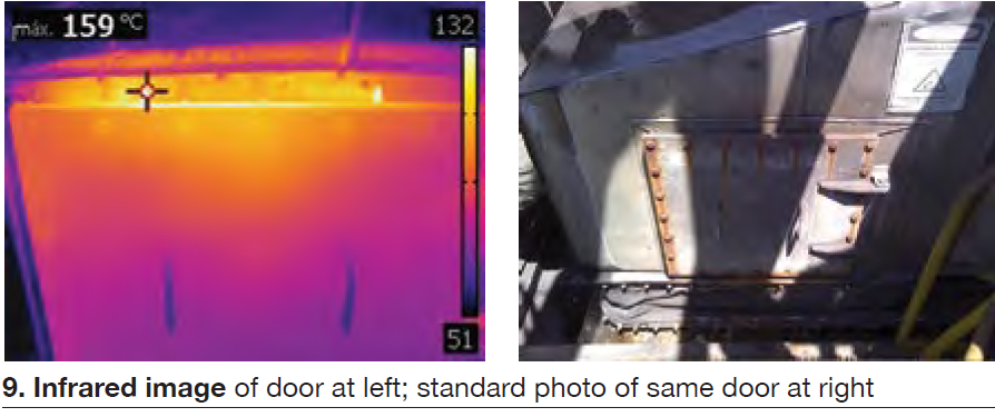
Infrared imaging inspections of the ducts can detect issues that could lead to excessive casing temperatures (Fig 9). Inspections should pay particular attention to the roof, doors, and pipe seals of the first three modules (HP evaporator and forward toward the combustion turbine).
The steam separators have been inspected, but their operation must be monitored. Testing of steam purity leaving the drums will ensure that downstream equipment is properly protected from carryover.
Examining flames through the burner viewports can verify that flame lengths are not excessive. OEM documentation will provide guidance, but a rule of thumb is that flames should be less than 10 ft long and not exceed two-thirds of the distance from the burner to the downstream tube face. Shorter is acceptable.
A review of operational instrument data can reveal troubling patterns with controls or equipment conditions. Excessive cycling of valves, valve leakage, excessive desuperheater spray water, and other harmful conditions can be determined from organization, trending, and examination of process and equipment data.
When piping is hot, movement may be more or less than calculated. If a pipe-support position indicator is significantly past the hot mark or short of the hot mark, stresses may be higher than anticipated. Support position indicators that reach the maximum travel constraint are a serious concern.
Years 2 through 5
Regular inspections. Every year or two after the first post-fire inspection, a standard inspection is recommended to look for wear issues throughout the HRSG. As conditions develop, they can be identified and the underlying cause corrected before large-expense outlays are required. These inspections normally take 10 to 20 hours per HRSG and focus on the gas path, header crawl spaces, steam drums, and exterior surfaces.
After four years’ time, issues that tend to be more time-dependent get more focused attention—including corrosion, expansion-joint failures, pipe seal failures, and fatigue cracking of pressure parts and liner systems. Inspections can be enhanced with aerial drones, borescopes, thermal imaging, magnetic particle or dye penetrant NDE, and online assessments as needed.
Analysis for changes and vulnerabilities
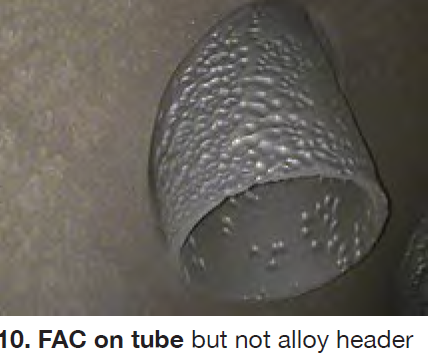 FAC risk assessment. Flow-accelerated corrosion may be the most detrimental and expensive of tube and pipe failures (Fig 10). Localized damage from FAC often occurs in major components or all components of evaporators and economizers. An external release of water and steam from FAC damage can be fatal to personnel. Highly dependent on water chemistry, damage from FAC can develop rapidly with visual wear occurring in less than one year. Some HRSG designs are more susceptible than others, and OEMs typically do not consider the owner’s water-chemistry programs.
The HRSG should be evaluated for risk of FAC before the third year of operation. A follow-on FAC inspection plan can then begin. However, your FAC mitigation program should begin earlier if there are telltale signs on FAC in the LP or IP drum in Year One.
An FAC risk assessment will look at each component of the HRSG and feedwater systems that has potential for either single- or two-phase FAC. Many HRSGs are now constructed using FAC-resistant materials in high-risk areas and in those cases, the scope or frequency of inspection can perhaps be reduced but should never be neglected.
Operational changes. Several years into operation, the owner may need an operating profile different from that specified for the original design. This could include cycling frequency, low-load operation, or perhaps a gas-turbine modification.
Some changes may be out of the owner/operator’s control. Power purchase agreements, changed market conditions, or new regulations could influence the number of starts, hours of operation, ramp rate, or combustion turbine output. Innovations in engine design may bring financial incentives to modify the gas turbine, and that invariably affects the HRSG and other equipment.
All should be evaluated for any new operating parameters contemplated. Examples include the following:
Cycling study Many owner/operator specifications will require the HRSG be designed for a certain number of starts per year. Each start causes wear and tear on the unit. Inspectors generally find that HRSGs operated at base load look much better than those that cycle often.
A cycling study will look at those components vulnerable to thermal transients, high temperatures, and low flow rates that often accompany startup and shutdown conditions. Cycles affect the allowable HP steam-drum ramp rate, so if startup time must be reduced or is in question, the cycling study will reveal the balance between cycle frequency and ramp rate.
Low-load operation. Operation of the gas turbine at low loads affects steam and water flow rates. This can lead to unstable flows in economizers and poor flow distribution in superheaters and reheaters, all affecting tube reliability. High exhaust temperatures from some turbines require excessive desuperheater spray that damages downstream pipes and tubes.
Gas turbine modifications. Turbine modifications primarily affect the HRSG through a change in exhaust mass flow and temperature. This changes the ratio of HP/IP/LP steam generation as well as overall heat recovery. Many components must be examined for suitable operation. Modifications with high exhaust temperatures may result in excessive desuperheater spray demand as well as superheater and reheater tube metal temperatures above the design temperature.
Avoid ongoing operations that damage the HRSG
Desuperheater leakage and excessive spray. The desuperheater is responsible for a significant share of damage to superheaters, reheaters, and steam pipes. In some cases, very few fatigue events are needed to initiate tube failures and cracks in the steam piping. There are two underlying causes:
First, there may not be enough energy in the steam to evaporate the spray water. This causes restrained thermal expansion and potentially high stresses in components that are quenched by the water droplets.
The steam temperature downstream of the spray nozzle should be more than 50 deg F above the saturation temperature. A review of operating data will reveal this potential problem. Installation of thermocouples on the exterior of the downstream pipe can reveal damaging conditions.
Second, damage to pipes and tubes often occurs when water flows through the spray nozzle without proper atomization. This is caused by a leaking block valve during periods of no spray water demand or from a broken spray nozzle. Water then can flow upstream or downstream through the steam pipe.
A drain pot with automatic detection and drainage is required on all new HRSGs with a desuperheater. In such cases it is important to verify that the drain pot will collect any leakage (sometimes it does not) and is functioning properly. Operators must be very careful if using manual operation of the pot drain valves or spray-water control and isolation valves.
Burner operation. Excessive heat can damage downstream tubes and duct-wall liner systems. Burner failures result in high localized heat input while faulty control logic can cause a wall of flame pushing through the tube banks.
Burner system controls must be checked as well. Burner output should be controlled to the limitations of the HRSG, not to the burner design maximum. This is especially important when multiple HRSGs have burners controlled to provide a minimum steam generation rate in a common header. If one unit goes offline or if some of the burner elements are isolated, how is the additional heat distributed among remaining units? It is important to verify that controls distribute heat as intended. Burner management system permissives and fuel-skid set points must prevent excessive fuel flow to any one HRSG.
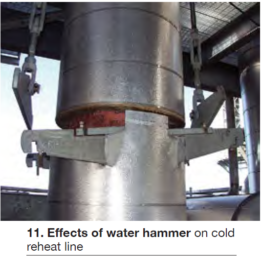 Piping and header drain control. It is critical to verify that low points in the steam pipe and tube circuits are properly drained and that there is no water leakage through steam conditioning systems. Undrained pipe can lead to water hammer with damage to pipe supports (Fig 11). The cold reheat system has been particularly susceptible to such events.
If water hammer does occur, it is important to inspect the damage and the position of the pipe. Water hammer could create a low point that did not previously exist. The reheat system can cause extremely expensive pressure-part damage if not maintained and operated properly (including sizing, location, and control).
After shutdown of the HRSG, steam will condense and flow to the lower headers of the HP superheater and the reheater. If this water is not removed prior to startup, steam can push water droplets up tubes or water can restrict steam flow. These conditions cause high stress resulting in tube failures.
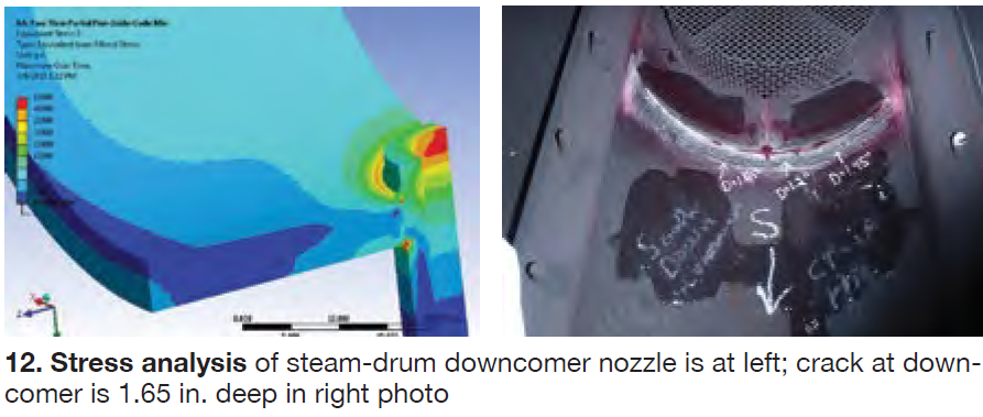
HP-drum pressure ramp rate. HP steam drums in cycling service are susceptible to fatigue cracking of nozzles, particularly the downcomers. Inspections have revealed cracks that extend over half of the lower shell-to-head weld, and up to half the thickness of the weld. Exceeding the maximum ramp rate will increase the risk of such cracking.
A complete understanding of the basis for the ramp-rate calculation also is needed. If the purchase specifications required a specific ramp rate, it likely was based on a specified number of cycles. A future increase in the number of yearly cycles would yield lower recommended ramp rates. If the number of yearly cycles increases beyond what was specified, cycling analysis along with additional FEA analysis of the drum can produce new ramp curves (Fig 12).
Training. To tie in all that is learned from the inspections, industry practices, OEM design considerations, current operations and lessons learned, it is beneficial to bring the operators and stakeholders together in one place for operator training. Information can be shared among all to improve consistency in operation and to achieve common ground on those practices, concerns, and goals that are most important. CCJ