


By Dave Lucier, PAL Turbine Services LLC
Turbine Tip No. 3, from the PAL O&M solutions library, applies to General Electric Frame 5 models K-LA and M-P, early 6Bs, 7Bs, and 7Cs.
Gas-turbine auxiliary systems require periodic maintenance to assure that your engines achieve the availability and reliability metrics necessary to satisfy plant and grid operational objectives. Often taken for granted and not regularly serviced are the following fluid systems:
- Lube oil and/or hydraulic supply.
- Coolants (cooling water).
- Fuels (gas and liquid), fuel nozzles, and check valves.
- Atomizing air (if liquid fuel).
- Cooling and sealing air for turbine bearings.
- Control air (if pneumatic controls).
- Fire protection (CO2).
Auxiliary devices that rely on these systems include:
- Diesel starting engine.
- Torque converter.
- Jaw clutch.
- Rotor ratcheting device (or turning gear).
- Fuel regulator.
- Spark plugs and flame detectors.
- GEMAC and 65EP temperature control transmitter.
- Fuel nozzles and related check valves.
- Liquid-fuel forwarding and treatment skids.
- Compressor bleed air (10th– to fourth-stage recirculation).
Here’s an example of a systems issue:
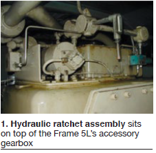
A user was having difficulty with the reliability of the hydraulic ratchet (rotor turning mechanism) shown in Fig 1. It wasn’t stroking reliably during the startup of a Frame 5L gas turbine. It often did not turn the rotor with the “breakaway torque” required to assist the starting means (diesel engine). Also, it often was unreliable during engine shutdown when required for uniform cooldown after the rotor coasted down to 0 rpm.
Note that the OEM recommends the rotor be ratcheted about 15 degrees every three minutes to assure uniform cooling after fired operation. The unit should remain “on ratchet” until the turbine-section wheel-space thermocouples drop below 200F—usually many hours.
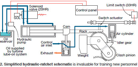
In this case, the dc motor and pump (88HR) were tested and found in good working order (Fig 2). The four-way sequencing valve (20HR) also was tested, as was the hydraulic ram and pneumatic engaging mechanism. Oil depth in the sump feeding the pump suction was verified as adequate.
Later, when a starting attempt was made, operators found that the lube-oil header feeding the generator pedestal bearing would not close—and this is a permissive to activate pressure switch 63QT. Thus, the start attempts kept aborting. Finally, inspection of the lube-oil system filters was suggested. They were clogged!
Note that filter manufacturers generally recommend that cartridges installed in oil systems should only function as “one year wet.”
The above example underscores the need to regularly change lube-oil filters. But the old expression “never ‘assume’ anything” is well reinforced: It makes an ASS of U & ME! Regular (planned) maintenance of the lube-oil filters would have saved several days in troubleshooting, plus the associated cost of field engineering services.
Seemingly unrelated to the ratchet system, the lube-oil supply was insufficient (at times) to keep the feed sump adequately filled.
GE provides owner/operators some useful piping diagrams along with their associated device summaries. Each fluid system is described in a detailed schematic that includes a list of supporting drawings as well as an explanation of abbreviations and symbols used by the OEM.
The referenced drawings are useful because they depict how a given system functions. It usually is possible to “trace out” and entire system to find out where the individual devices are installed. Others may be familiar with similar P&ID system drawings.
The accessory-base design for GE engines changes from model to model. For example, the accessory base for a Frame 5L differs from a 5P in many respects. Similarly, by necessity of design, a two-shaft Frame 3 compressor drive will be arranged differently than a single-shaft generator drive. Frame 5s have integral accessory bases; Frame 7B, C, and E engines, and some Frame 6Bs, have separate accessory bases.
The first documents I seek out upon arrival to a jobsite include these schematics. My philosophy is that you can’t fix it if you can’t find it. Furthermore, I want to trace-out the schematics to find components and verify their condition on Day One.
Another important set of documents to have in hand are the control specifications, specifically the control-system settings. These documents and performance graphs help in knowing the proper settings and adjustments of the auxiliary systems in advance of trying to start and operate the gas turbine.
The importance of meeting expectations with respect to availability and reliability was mentioned in the first paragraph. Bear in mind that if the control-panel master selector switch is set in the remote position, the powerplant generally is thought to be “available” to run when dispatched. Starting reliability is a particularly important metric for “black-start” units. And, if the plant has a “dead-bus” starting feature, the engine is expected to start when line voltage is sensed to be zero.
It is not possible to achieve these goals unless the recommended maintenance for your gas-turbine and generator auxiliary (fluid) systems is performed regularly and rigorously. CCJ