Gas Turbine Historical Society
Jurassic turbine keeps on ticking
By Rodger O Andersen, DRS Power Technology Inc
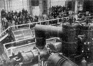
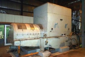
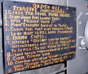
Back in the Jurassic era, when your elementary school teacher used a mimeograph machine (and the scent presaged your college days), when a guy in a swim suit jumped off a cliff in Hawaii hawking a Timex watch on your rabbit-eared television, a Dresser Clark gas turbine came into existence.
Well, okay, it was 1960 but in machine time, that’s a dinosaur of a turbine. Yet the owner of that turbine, the epitome of low tech today, still extracts huge value from it, deploying it as a peak shaving unit and capacity resource.
Let’s examine the fossil record
The original machine served admirably at a naval test facility for a few years. After its honorable discharge, with plenty of value to spare, Northwestern Wisconsin Electric, a small utility, bought it and repurposed it for peaking service in 1981 (Sidebar 1). In the late 1990s, the unit suffered from airfoil damage and a failed expansion joint (Fig 1).
The blade issue wasn’t too big a deal but the utility was ready to scrap the unit because replacing the expansion joint would require a complete disassembly of the engine. Just before the machine was headed for the bone yard, the utility accepted an alternative solution, which proved successful. In late 2002, the unit was put back in peaking service.
No one would dare suggest that this was an agile dinosaur. Even back in the day, it was probably related to brontosaurus, not
triceratops. The Dresser Clark model 302 delivers 7 MW with a firing temperature of about 1300F and a pressure ratio of about four. The torso is a 15-stage axial compressor, the legs a two-stage HP turbine running at 4600-4700 rpm. The power turbine, also two stages, turns at 3600 rpm.
The large reverse-flow combustion chamber (Fig 2) is supported directly over the compressor case. Liquid fuel feeds the hungry beast through eight burner nozzles. The machine even sports a hopper and valve for
injecting rice or ground up walnut shells for compressor cleaning. When the
machine needs to quit running, an emergency stop lever is pulled to close dampers in the inlet duct and starve the machine of air (Fig 3).
Like most dinosaurs, this one requires a lot of surrounding real estate. Skid mounting of the lube oil system wasn’t common practice in Jurassic times. This machine has an oil system that takes up 900 ft2 (Fig 4). The machine itself is mounted on a large barge-shaped steel base frame.

Takes a licking
In its reincarnation, the DC 302 held its turf for many years, giving 50 to 100 hours of operation annually to the utility. But dinosaurs get wounded, too, and this one was almost left for dead. In August 1999, combustion problems resulted in damage to the turbine blades and vanes.
After repairs were made, some compressor blades were damaged but the machine still shivered with vibration. Finally, by April 2001, it appeared that the machine was back in good health. Just as it was reaching full power, the downstream side expansion joint between the combustor hot casing and the turbine case blew out (Fig 5).
This wasn’t just a hole in the skin that could be stitched up. The expansion joint is a 360-deg, 7-ft-diam ring that would require a complete disassembly of the unit to replace. An 18-in. section of the thin split tube had ruptured and the wound was not accessible for weld repair. The cost was pegged at $300,000 and the owners suspected other major problems with the engine. Only an in-situ repair for very low cost could be tolerated; otherwise this dinosaur was on the road to extinction.
Fortunately, a second opinion revealed a practical, far less expensive alternative. The combustion hot casing is supported

by flex rods that allow expansion in all directions. Thermal expansion calculations showed that a single joint was capable of handling the total expansion of the hot casing relative to the turbine casing. The damaged part of the joint could be abandoned in place by covering it over with a continuous strap (Fig 6) seal welded to both the hot casing and the turbine casing.
The specific steps in the surgery were the following:
- Remove the 192 bolts that held the expansion joint between the two casings.
- Cut sections of 0.125-in.-thick steel strips, bent to the correct curvature.
- Seam weld the strips to the expansion joint, then butt weld the strips to each other to form a continuous overlay.
- Fit the straps under the bolts and nuts on the flange that mates with the
combustion hot casing and over the bolts and nuts on the flange that mates with the turbine casing. - Reinsert the 192 bolts and tighten.
During the same period, the turbine rotor and nozzle casings were disassembled to correct rub-related rotor vibration (Fig 7). The inter-stage seal mounted on the second stage turbine nozzle was rubbing on the first and second stage turbine discs. Seal surfaces were hand ground to increase radial clearances. The entire machine was then reassembled.

Roaring back to life
Initial startup for the reconditioned machine occurred in late November 2002, nearly three and a half years after the unit was forced out of service. It ran for one hour synchronized to the grid and half that time it delivered 6.1 MW.
Rotor vibration was acceptable and the soundness of the expansion joint solution was demonstrated. But fuel system pressure swings caused the turbine to trip and there was still a problem in the bearing tunnel. After the engine warmed up, a blue cloud of smoke (Fig 8.) would emanate from the tunnel that would eventually fill the turbine building (Sidebar 2).
As noted earlier, this dinosaur isn’t winning any Darwin awards for efficiency and agility. Its heat rate is nearly 20,000 Btu/kWh, so it sucks up fuel. But it earns its keep even in hibernation because the owner receives capacity payments for having the megawatts available.
But the legend around this machine doesn’t end here. Distillate fuel is expensive and natural gas isn’t these days. Previously, the utility had purchased a retired high-pressure unit for spare parts (Fig 9). While the casing and expansion joints of the spare had slightly different dimensions, it turned out that its gas fuel manifold and cover would fit the reconditioned unit.
The owner verified that the nozzles could handle the flow at the delivery pressure of the gas supplier in the area, added control valves for the gaseous fuel, and replaced the liquid-fuel manifold with the gas-fuel manifold from
the spare. Today, this fossil of a turbine can operate on the less expensive fossil fuel or fire up on the original fuel. CCJ


